
Steel structure splicing includes splicing in the workshop and on-site. The splicing methods include welding and bolting. We should implement…
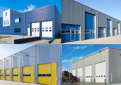
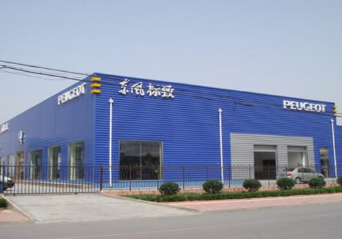
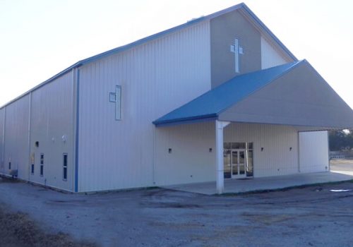
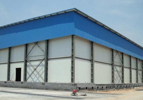
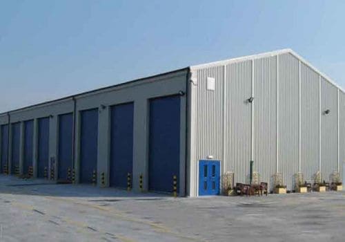
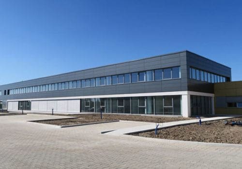
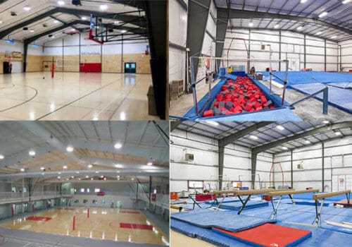
The portal steel frame buildings are standard steel structure. Its appearance is similar to that of a door frame. It has a large span and is widely used in industrial plants, warehouses, and other buildings. This structure has the advantages of being lightweight, high strength, strong bearing capacity, large span, and convenient construction, so it has been widely used in industrial buildings.
What is a portal steel frame?
1.1 Definition and basic concepts of portal steel frame
A portal frame is a plane system structure composed of side columns and diagonal beams connected by rigid connections. It is often used in large factories, warehouses, and other buildings. Hinges usually connect the portal steel frame’s column base, and the design of the hinged connection is critical, especially when the factory is built on a soft soil foundation. A rigid connection is more appropriate when the building needs to withstand large cranes, local mezzanines, or high eaves.
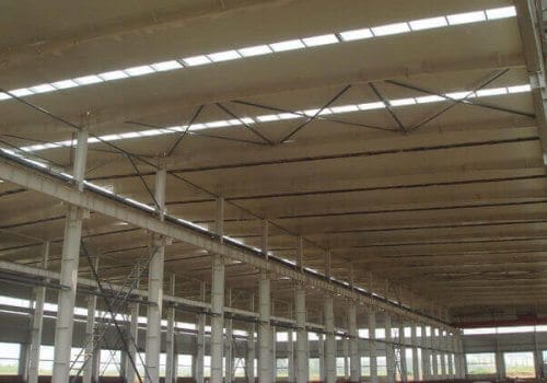
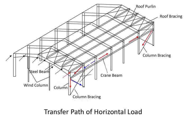
The portal frame’s main feature is a rigid connection connecting the middle column with the diagonal beam. The support system usually consists of horizontal roof bracing and column bracing. The bracing system is arranged perpendicular to the portal steel frame to form a truss structure, constituting a spatially stable structural system with the plane portal steel frame.
The main components and design features of the portal steel frame:
1. Main structure:
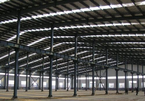
Steel columns and roof beams: The primary structure’s steel columns and roof beams can be solid H-shaped or lattice steel components. To save steel, the components are usually designed as variable cross-section forms according to the distribution of the bending moment diagram.
Column foot connection: The design of the column foot can be a rigid or hinged connection according to the building’s rigidity requirements. Although the amount of steel used for solid web components is large, the structure is simple, the construction is convenient, and it is widely used.
2. Secondary structure:
Roof purlins and wall girts: Roof purlins and wall girts are generally arranged on the main structure of the portal steel frame to support various loads on the enclosure system. The secondary structure usually uses cold-bent, thin-walled steel components. Truss purlins are more economical if the column distance exceeds 12 meters.
3. Bracing system:
Cross-bracing: The bracing system often uses cross-bracing to improve the economy. When cross bracing cannot be used for column support, beam-column portal bracing can be used. The bracing system not only supports the main structure but also provides lateral support to enhance the overall stability of the main structure.
4. Roof and wall:
Enclosure structure: The roof and wall are generally made of corrugated metal sheets or other lightweight materials, which are connected to the secondary structure in a certain way to withstand loads such as wind, snow, and construction.
5. Special design:
Crane bracing: When a crane weighing more than 5 tons in the structure, the roof and column bracing must be designed as a tie rod type, using tensioned cross-round steel supports. Column supports can be made of angle steel or other steel.
Advantages of portal steel frame:
Compared with reinforced concrete structures, portal steel frame has many advantages:
Lightweight: The steel structure is lighter and suitable for large-span buildings.
High rigidity: The portal steel frame structure has good rigidity and can withstand large loads.
Flexible design: The portal steel frame is flexible and can be adjusted according to needs to adapt to various building forms.
Reasonable force: Since steel is the primary structural material, the portal steel frame performs well in force.
Convenient construction: The portal steel frame’s prefabrication and assembly methods are simple and fast, with a short construction period and high economy.
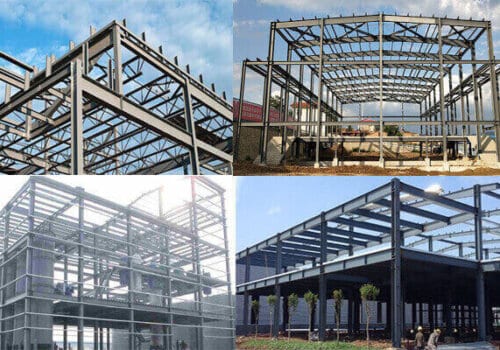
Forms of Portal Steel Frame Buildings
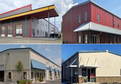
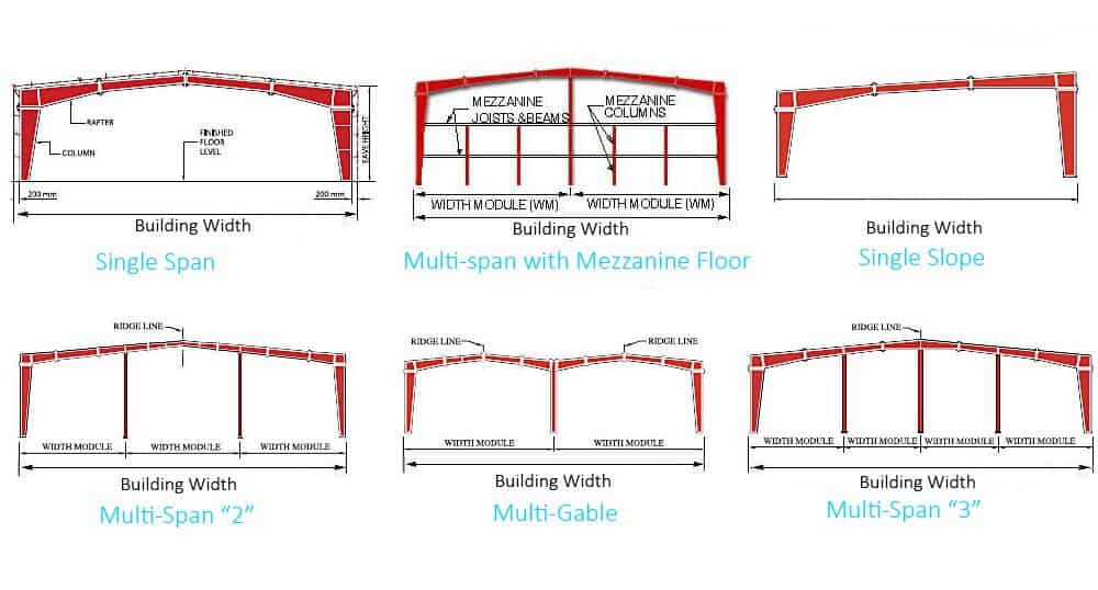
The structural forms of portal steel frames are diverse, and the common ones are single-span, double-span, high-low span and multi-span types. The roof forms can be divided into single-ridge, multi-ridge, single-slope, double-slope, multi-slope and flat slope. These different forms of steel frames can be flexibly selected according to the functional requirements and design requirements of the building.
Single-span steel frame: suitable for buildings that do not require too much horizontal space, and the span is usually between 18 meters and 36 meters. The beams and columns of the single-span steel frame are mostly welded or rolled H-shaped steel, and are accurately positioned and adjusted in height according to the span and bending moment distribution diagram, which has good economy and structural simplicity.
Double-span and multi-span steel frames: suitable for large buildings, which can provide wider space and higher bearing capacity. The cross-sectional area of this type of steel frame is usually similar to that of the single-span steel frame, but its central column has an equal cross-sectional area, which increases the stability and bearing capacity of the structure.
At present, with the continuous advancement of design and construction technology, the maximum span of the portal steel frame can reach 72 meters, further meeting the needs of modern large-space buildings.
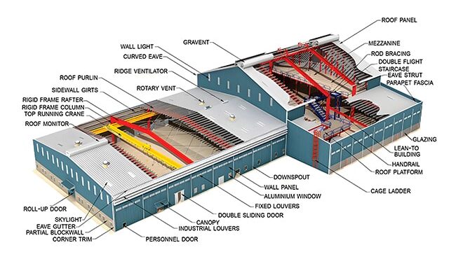
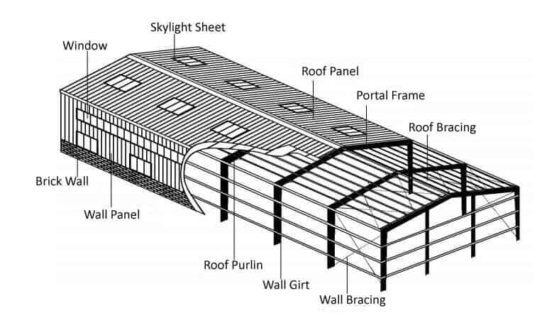
The composition of Portal Steel Frame Buildings
- Primary framing includes transverse rigid frames (including middle and end rigid frames), floor beams, crane beams, support systems, etc.
2. Secondary framing: roof purlin and wall girt, etc.
3. Envelope structure: roof and wall panels;
4. Auxiliary structures: stairs, platforms, handrails, etc .;
5. Foundation.
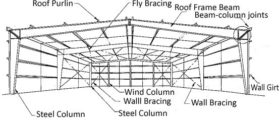
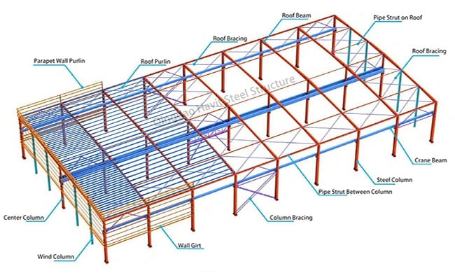
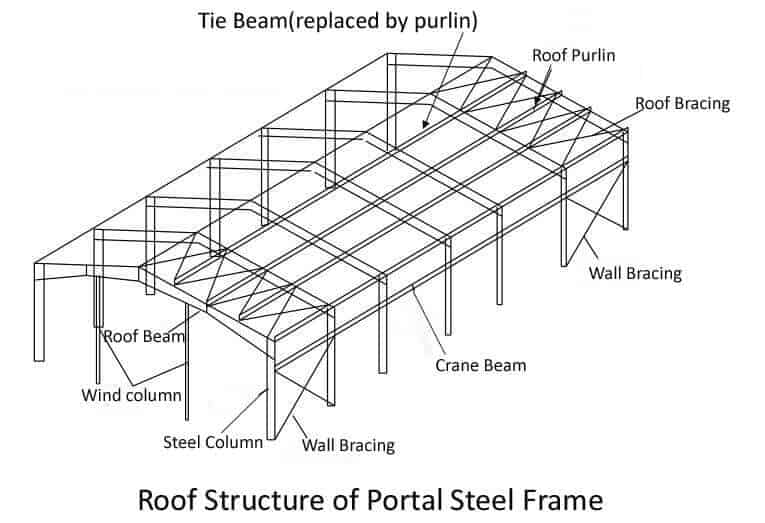
The primary force skeleton of portal frame steel buildings comprises steel columns, roof beams, and bracing systems. This is considered to be the primary framing. The roof and wall panels act as the envelope and closure for the structure, enhancing its overall stiffness. The roof purlins and wall girts also support the roof and walls and lateral support for the main structural beams and columns, forming the secondary framing.
The Connection Details of Portal Frame
Pre-embedded parts and Column Foot:
Pre-embedded parts
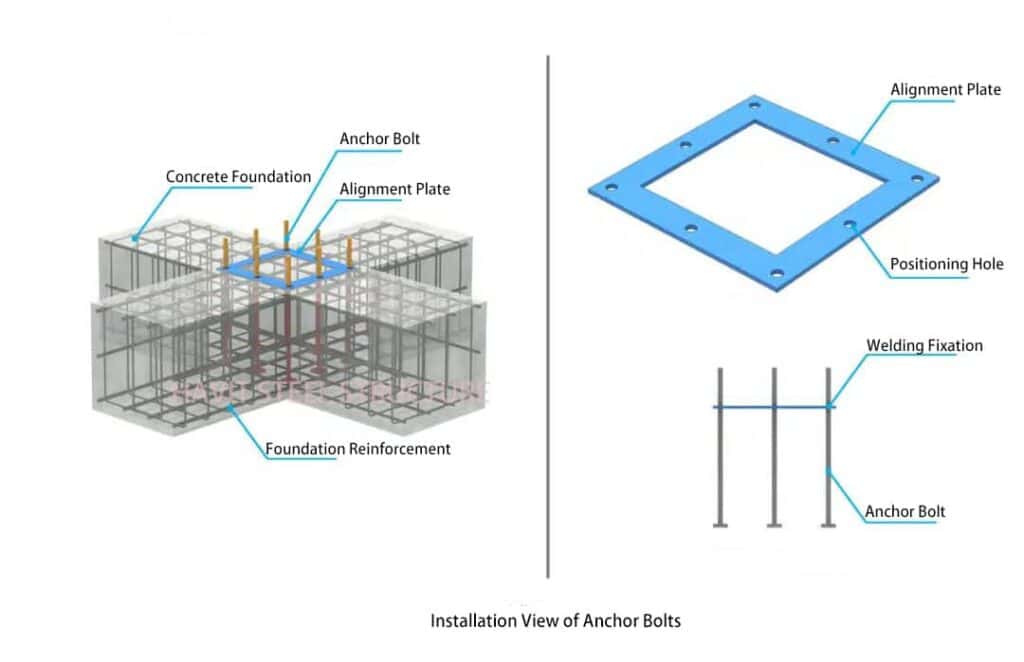
- Foundation anchor bolt construction process:
(1) Binding of steel bars.
(2) Positioning and marking.
(3) Installation of positioning plates.
(4) Fixed positioning plates.
(5) Installation of anchor bolts.
(6) Welding Fixed.
(7) thread protection. - Besides the upper part of the anchor bolt being welded to the positioning plate, the lower part should be fixed with the underlying steel bars using steel ties after the measurement and review of positioning are completed.
- The shear groove must be pre-embedded and installed simultaneously.
- The wire mouth is lubricated with butter and then wrapped with tape or a unique sleeve for protection.
Hinged column base:
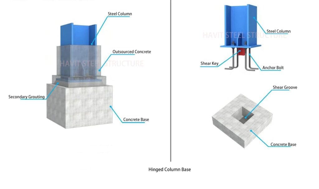
- Steel columns with hinged column feet need to be fixed with cables during the installation stage, with wedge-shaped iron blocks at the bottom to assist in fixing, and they should be connected to adjacent steel columns promptly to form an overall stable structure:
- After the steel column is corrected, secondary grouting is performed. The upper part of the short column foundation is treated with latent hair. The grouting material should have micro-energy tensile properties. The thickness of the secondary grouting layer should be no less than 50mm and no more excellent than 100m.
- The shear groove must be cleaned and chiseled before the steel column is installed, and the dimensions must be reviewed. There must be no foreign matter inside:
- The anchor bolt pad and the steel column foot plate are welded and fixed. The welding specification is fillet welding, and the height shall not be less than 1/2 of the pad.
- Enough operating space must be reserved for tightening the anchor bolt nuts during the in-depth design stage.
Rigid column base:
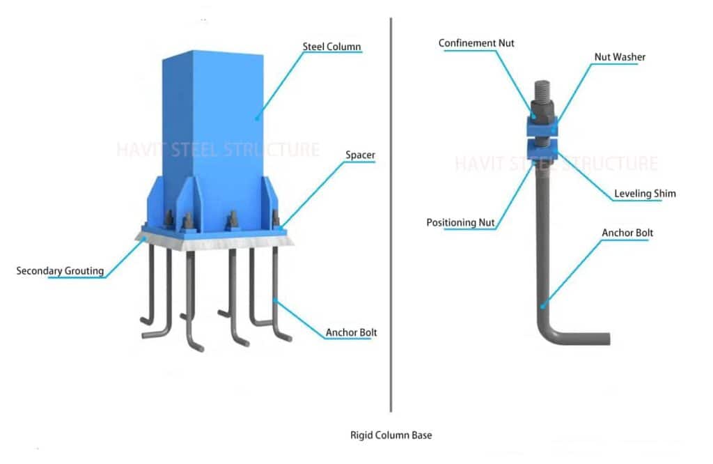
- The design of the anchor bolts for rigidly connected columns is no less than 6, and the steel columns and anchor bolts are rigidly connected:
- During installation, the rigid column feet can form a stable unit, and the secondary grouting layer can be constructed after the correction. The thickness of the secondary grouting layer is generally not less than 50m and should not be greater than 10m.
- Generally, shear keys are not provided for rigidly connected column bases.
- Two fastening nuts are fixed by welding: the backing plate and the steel column bottom plate.
Bracing System for Portal Frame:
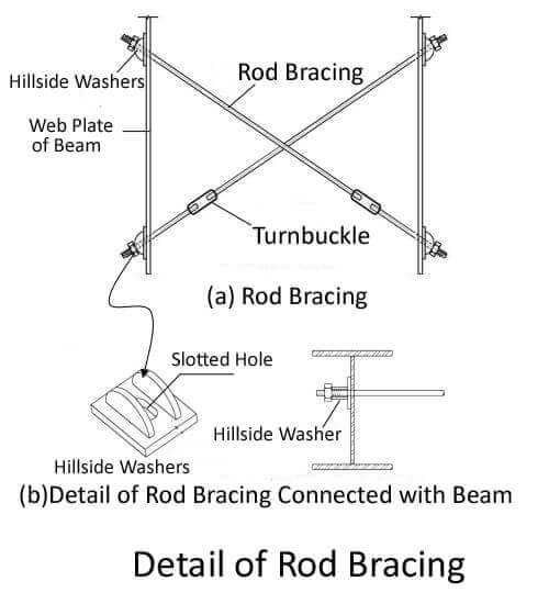
Inter-column Rod Bracing
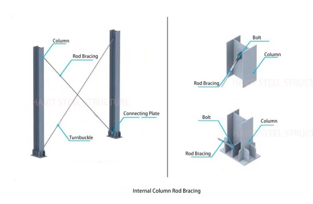
- Inter-column rod bracing is generally suitable for columns and is matched with a pipe strut to form a bracing system:
- The double-sided welding of rod steel and steel plates is completed in the factory, and the single-hole dumpling connection with connecting bolts is used on-site to connect the steel columns:
- The turnbuckle is tensioned and installed on two adjacent rows of steel columns. After correction, tools are used to tighten it. The tightening standard is that the round steel be tight and straight.
Inter-column Angle Bracing
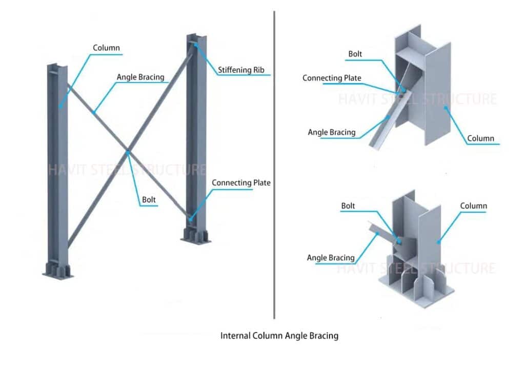
- The inter-column angle bracing is installed synchronously with the steel columns, and adjacent unit steel columns, steel beams, and other structures are installed sequentially as stable units;
- High-strength bolts connect the angle bracing and the connecting plate, and after tightening, the angle steel is connected to the steel plate.
Roof Horizontal Rod Bracing
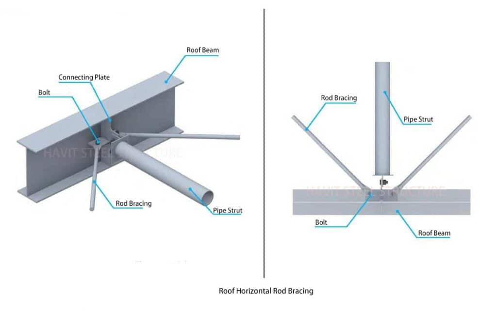
- The roof horizontal rod bracing installation time is synchronized with the roof beams to increase structural stability.
- The round steel support is tightened with turnbuckle screws.
- Round steel supports can be constructed using steel beam web joints.
Roof horizontal Angle Bracing
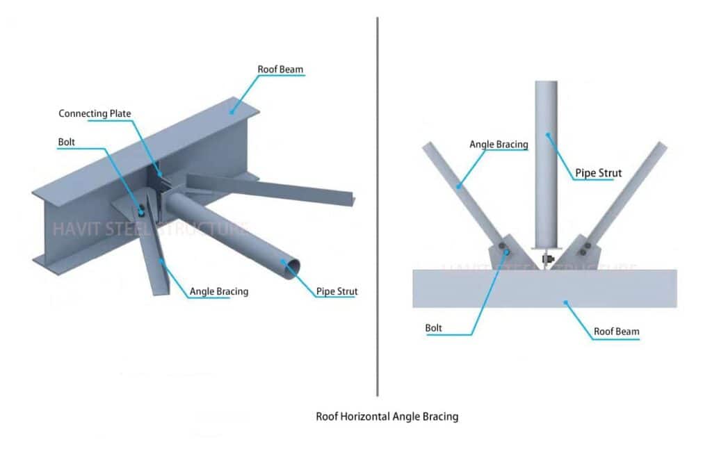
- To increase structural stability, the roof horizontal bracing should be installed simultaneously with the roof beams. During installation, the lifting point should be set straight at 1/3 to avoid deflection of the angle steel.
- The angle steel and the connecting plate are connected with bolts.
Beam-column connection
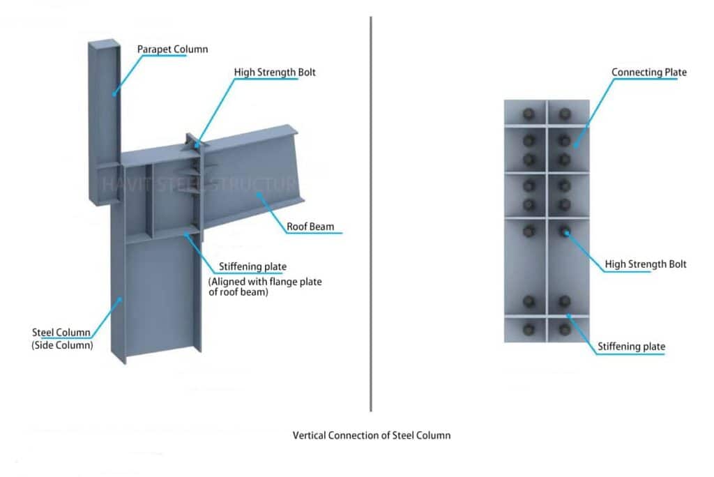
Vertical Connection of Steel Column:
Horizontal Connection of Steel Column:
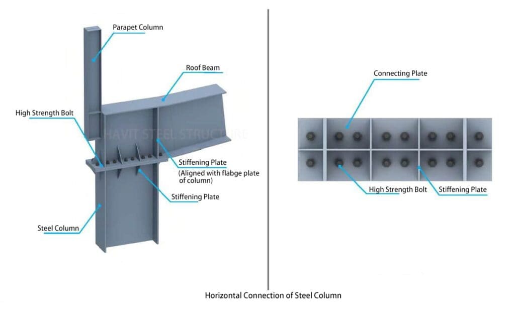
- The beam-column connection end surface is a friction surface.
- The final tightening sequence of high-strength bolts is gradual from the middle to the upper and lower sides. After the final tightening, the connecting surfaces are close to each other without gaps:
- Main control items: steel column verticality, column top elevation, steel beam elevation.
- The spacing requirements for easy tightening of high-strength bolts should meet the maximum allowable edge distance requirements and the minimum allowable edge distance.
Center Column
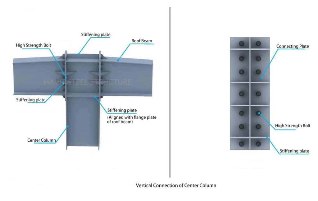
- The final tightening sequence of high-strength bolts on the connection surface is gradually from the center to the left and right sides. The steel beams on both sides are tightened symmetrically. After the final tightening, the connection surfaces are close to each other without gaps.
- Main control items: steel column verticality, column top elevation, steel beam elevation.
Wind Column
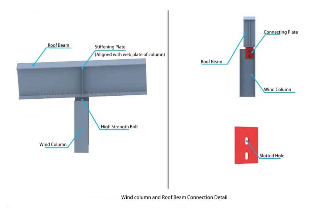
- The primary function of the wind column is to transmit the wind load of the roof.
The upper part is transmitted to the roof system by connecting the hinged node and the steel beam. As for the entire rack load-bearing structure, the lower part is transmitted to the foundation through the connection with the foundation: - Since the wind column does not bear the vertical roof structure load but only the surface wind load, the installation nodes of the wind column should be installed after the roof beams are installed.
Roofing beam connection
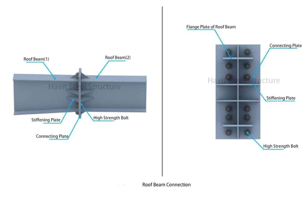
- After passing the requirements, roof beams should be pre-assembled in the factory and transported in sections to the construction site.
- Two or more sections of steel beams between columns can be assembled into a hoisting unit on the ground and then hoisted as a whole. The high-strength bolts should be finally tightened on the ground.
- Tighten the high-strength bolts promptly after connecting and installing the steel beams.
Roof C-shaped purlins
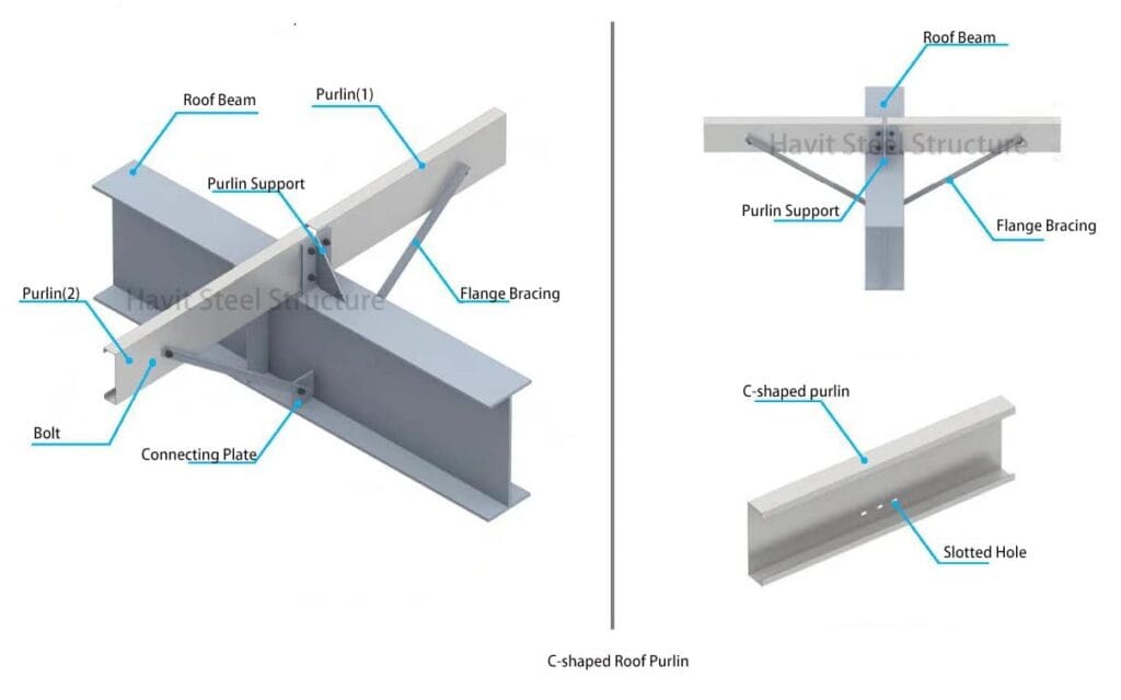
- C-type purlins are generally galvanized and pressed with steel strips.
- Purlins and connecting plates, purlins, and flange bracing are associated with C-grade ordinary bolts.
- A safety net must be hung on the lower part of the purlin before installation, and a lifeline should be set on the steel beam as a safety protection measure for workers:
- Expanding the steel beam’s flange width or increasing the number of tie rods can reduce or eliminate the setting of flange bracing.
Roof Z-shaped purlins
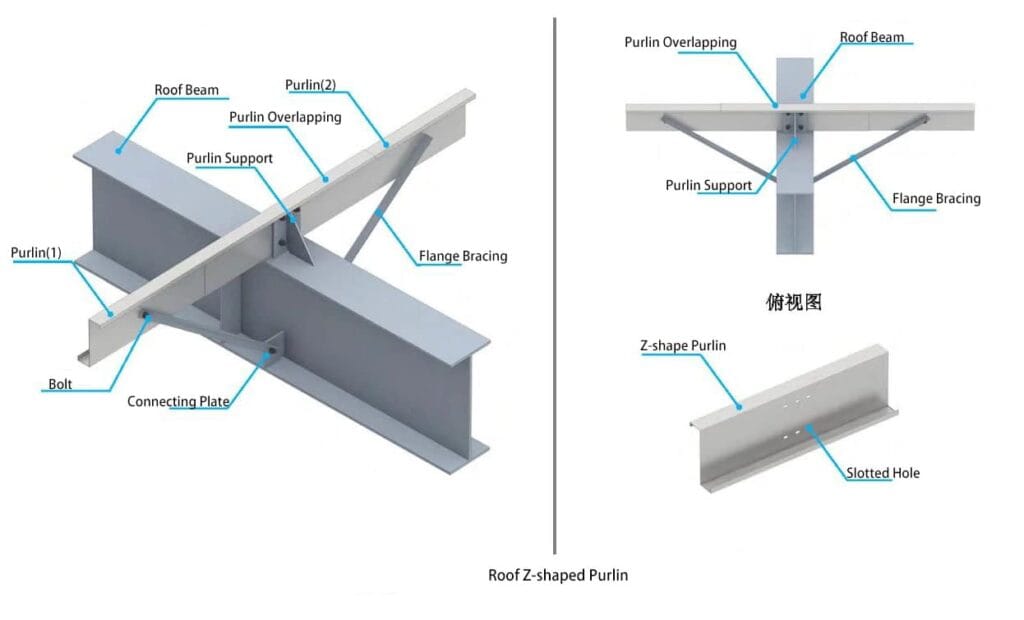
- Z-shaped purlins are generally galvanized.
- The purlins are connected and fixed with the steel beams using ordinary C-grade bolts through the purlin support. The purlin support and steel beams are welded into a whole body at the factory and coated with corresponding primers in the middle.
- Expanding the steel beam’s flange width or increasing the number of pipe struts can reduce or eliminate the setting of flange bracing.
Gutter
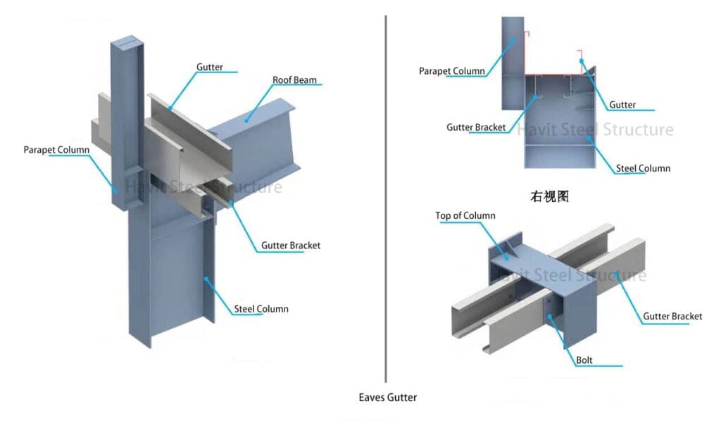
- Gutters are generally made of folded galvanized steel sheets or stainless steel. The blanking size is the unfolded width. When the gutter unfolded, the width was more significant than 1.5m, and a gutter operating pole should be installed.
- The gutter is connected by welding, and the stainless steel gutter uses matching stainless steel electrodes or wires made of the same material:
- The gutter and purlins are fixed with screws, and the parapet columns are fixed with break welding.
Flange bracing and Tie rod
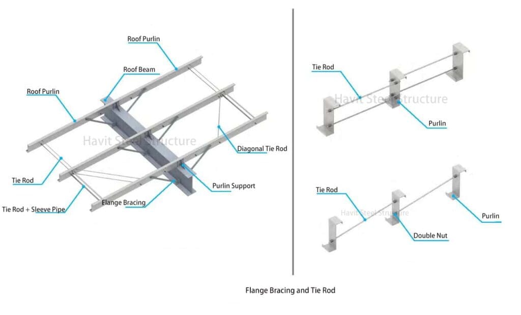
- The tie rod installation sequence starts with installing the sleeve pipe and diagonal tie rod, usually the roof ridge or cornice. After accurately positioning the purlin through the diagonal tie rod and sleeve pipe, the remaining braces are installed in sequence.
- The coating of tie rods and sleeve pipe should be galvanized.
Wall girt
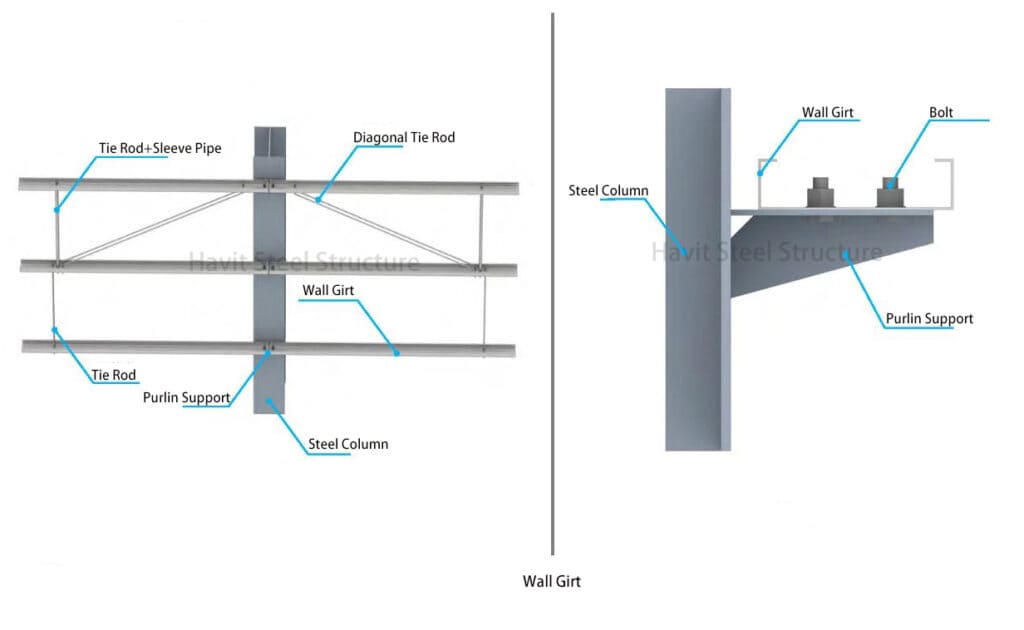
- The purlin support and steel columns are made uniformly in the factory and are painted according to the steel column coating requirements:
- Purlin control points: levelness, elevation, positioning of door and window openings, and whether they are fastened.
- The upper and lower purlins of the window frame should use double-purlins or square steel, and the C-shaped purlin openings on the side should face outside the window frame.
Crane beam bracket
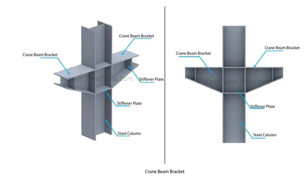
- The crane beam bracket and steel columns are welded together in the factory.
- The verticality of the steel columns and the top surface of the corbels are installed on-site as the primary control items.
Crane beam
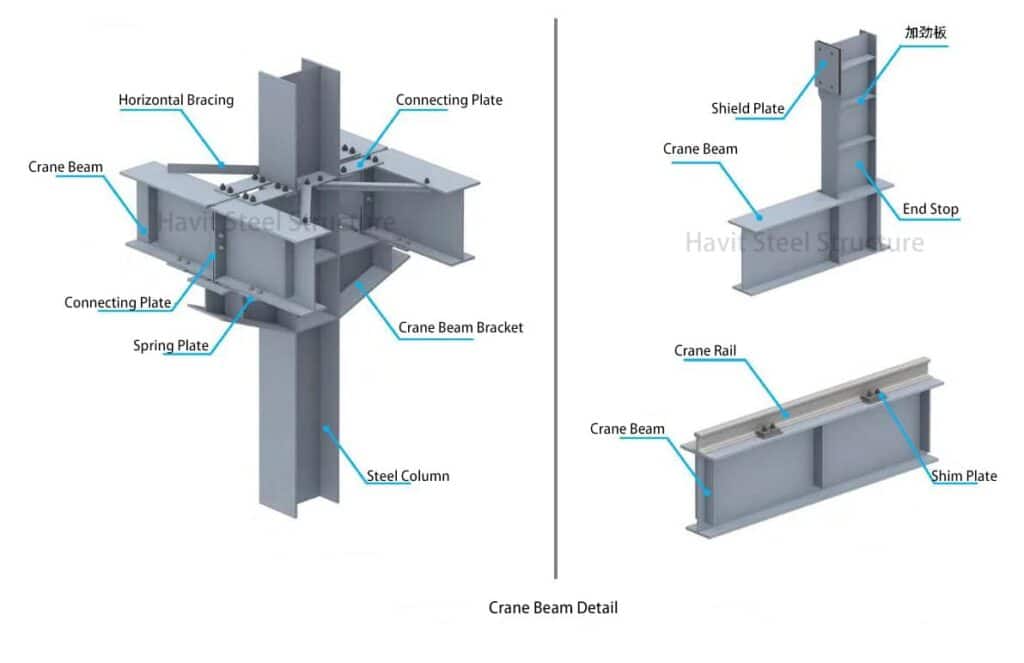
- Crane beam installation sequence: (1) steel column installation, (2) roof beam installation, (3) pipe strut and bracing installation, (4) correction (5) secondary grouting of column feet, (6) crane beam hoisting ( 7) Install connecting plates and flange bracing (8) Install adjacent crane beams (9) Connect and fix crane beams (10) Correction (11) Weld spring plates (12) Installation completed.
- After the crane beam is hoisted and the connecting plate is installed, the hook can be loosened to hoist the next steel beam.
The primary force skeleton of portal frame steel buildings consists of steel columns, roof beams, and bracing systems. This is the primary framing. The roof and wall panels act as the structure’s envelope and closure, increasing overall stiffness. The roof purlins and wall girts not only support the roof and walls but also provide lateral support for the main structural beams and columns, forming the secondary framing. The portal frame typically spans 9 to 36 meters, so if the side column widths differ, their outer sides should be aligned.
The recommended height of the portal frame ranges from 4.5 to 9.0mm, with a maximum height of 12m if an overhead crane is present.
To ensure proper structural integrity, the spacing between the axis of the column grid in portal frame steel buildings should fall between 6 and 9 meters. The overhang length should also be determined based on the specific application requirements, typically ranging from 0.5 to 1.2 meters.
The structural system of the portal steel frame buildings:
1. Transverse load-bearing structure:
- The transverse load-bearing structure comprises steel roof beams, columns, and foundations.
- This structure supports and transfers both vertical and horizontal loads.
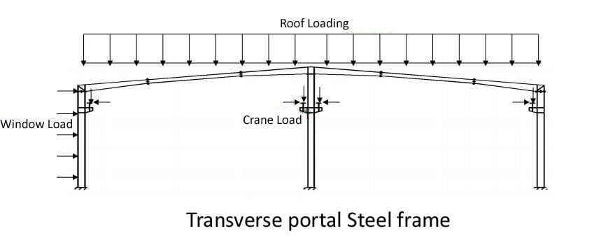
2. Longitudinal Frame Structure :
The longitudinal frame structure comprises longitudinal columns, crane beams, wall bracing, rigid tie beams, and a foundation. Its purpose is to maintain the building’s stability and rigidity along its length and to support and withstand various forces, such as longitudinal wind loads, horizontal crane loads, thermal stresses, and seismic effects on the gable and roof.

3. Roof structure
1). The roof panel is designed to withstand both horizontal and vertical wind loads on the roof. It is commonly made using a single-color metal sheet or sandwich panel.
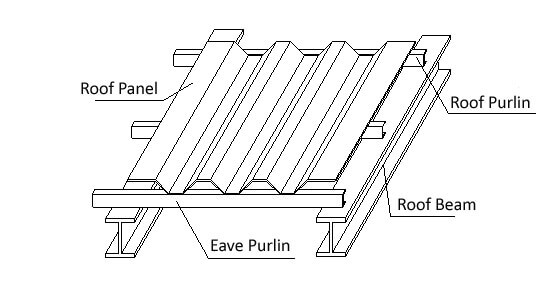
2). A purlin serves as a support structure for the roof panel and can bear both vertical and horizontal wind loads transmitted from it.
3). The rigid frame beam is a critical load-bearing component responsible for carrying the weight of the roof structure and any live load transmitted from the roof panel.
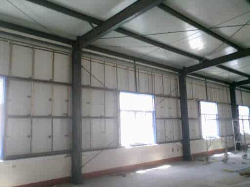
4. Wall structure
1). The exterior wall panels, which include the vertical and gable walls, are primarily responsible for withstanding wind loads. These panels are commonly made from single-color metal sheets or sandwich panels.
2). A wall girt is designed to bear both vertical and horizontal wind loads transmitted by the wall panel.
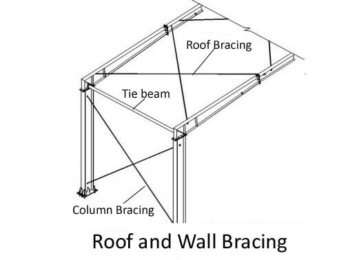
5. Bracing
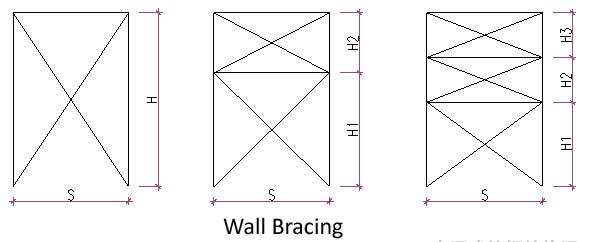
Type: Roof horizontal bracing, wall bracing.
1). The horizontal bracing comprises roof cross bracing, tie beam, and fly bracing. Its primary function is to increase the roof’s overall rigidity.
2). Wall bracing is implemented to enhance the stability of the wall frame structure.
Use:
1). Improving the structural rigidity of the building’s interior space.
2). Guaranteed structural stability.
3). Transmit wind load, crane brake, and seismic load to the load-bearing members.
External loads impact the structure’s envelope. The secondary structure carries the vertical and lateral forces to the lateral portal frame of the primary system. The portal frame’s resistance to external influences is dependent on its stiffness. The roof and wall bracing transmit longitudinal wind loads to the foundation.
The structural layout of Portal Steel Frame Buildings
The building’s requirements dictate the span and column spacing when designing the portal steel frame. Consequently, the critical factors to consider during architectural design are the bracing system layout and determining the temperature range.
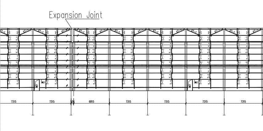
To account for the impact of temperature, longitudinal temperature sections of portal steel frame buildings must not exceed 300m, and transverse temperature sections must not exceed 150m. When the size of the temperature section surpasses the limit, temperature expansion joints must be implemented. These joints can be achieved by setting double columns or modifying the secondary framing.
The main principles of the Bracing arrangement are as follows:
- The distance between bracing is generally 30m-40m and should not exceed 60m
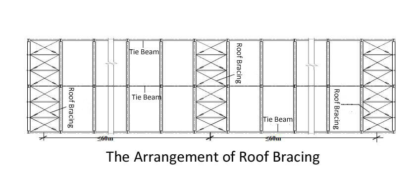
2. The horizontal roof bracing and the wall bracing arranged between the same column are used to ensure the formation of a geometrically unchanged system and improve the overall stiffness of the building structure;
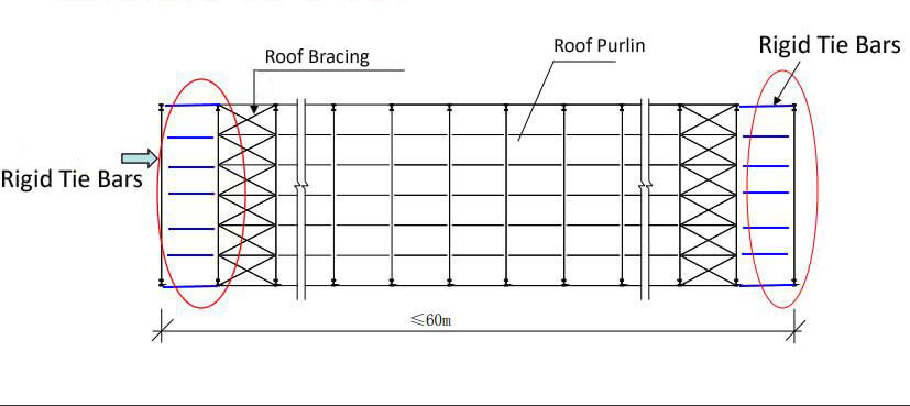
3. If the roof bracing is arranged between the second columns, rigid tie bars should be put between the first columns.
5. The 45 ° inclined bar can most effectively transfer horizontal loads. When the angle of the single-layer bracing member is too large due to the high column, the double-layer or three-layer wall bracing should be set;
6. Rigid tie bars shall be provided at the turning points, such as the column tops and roof ridges. Longitudinal rigid tie bars shall provide the structure longitudinally at the bracing truss nodes;
7. The rigid tie bar of the portal steel frame buildings can use the purlin at the corresponding position. The tie bar is provided when the stiffness or bearing capacity is insufficient.
The dimensions of the portal steel frame building should comply with the following requirements:
The span of a portal frame shall be the distance between the axes of the transverse frame columns.
The height of the portal frame should be taken as the height from the floor to the intersection of the column axis and the inclined beam axis. It should be determined according to the indoor net height requirements. For a factory with a crane, the height should be determined according to the rail top elevation and the crane net height requirements.
The vertical axis at the center of the lower end of the column can determine the column’s axis. The positioning axis of side columns in industrial buildings should be on the outside of the column. The axis parallel to the center of the minor end of the variable-section beam segment and the upper surface of the inclined beam can determine the axis of the inclined beam.
Construction dimensions of portal steel frame building:
The height of the cornice should be the height from the floor to the lower edge of the purlins on the outside of the house; its maximum height should be the height from the floor to the upper edge of the purlins at the top of the roof; its width should be the distance between the outer skins of the wall beams on the side walls of the house; its length Should be the distance between the gable wall beam skins at both ends.
The span of the portal frame should be 12 to 48 meters in a single span, with a module of 3 meters. If the widths of the side posts are not equal, their outer sides should be aligned.
The height of the portal frame should be 4.5 to 9.0 meters and can be increased appropriately if necessary. When there is an overhead crane, the height should not exceed 12 meters.
The spacing between portal frames, that is, the longitudinal distance between the axis of the column network, should be 6 meters, but can also be 7.5 meters or 9 meters, with a maximum of 12 meters. For smaller spans, 4.5 meters can be used.
The overhang length can be determined according to the usage requirements and should be 0.5 to 1.2 meters. The slope of the upper flange should be the same as the slope of the inclined beam. The forms of portal frames are divided into single-span and double-slope, double-span and single-slope, multi-span and double-slope, and rigid frames with overhangs and adjacent houses.
The connection between the middle column of the multi-span rigid frame and the inclined beam of the rigid frame can be hinged. Multi-span rigid frames should adopt double-slope or single-slope roofs. Multi-span rigid frames connected by multiple double-slope single spans can also be used if necessary.
Experience value of steel content of portal frame:
Light steel without a crane generally has a steel content of 30-40kg/㎡;
Light steel with a crane generally has a steel content of 40-50kg/㎡;
Heavy steel structure without cranes generally has a steel content of 60-80kg/㎡;
Heavy steel structure with cranes generally has a steel content of 80-120kg/㎡;
Purlin steel content is generally 9-12kg/㎡
Experience value of steel content of the portal frame; what are the main influencing factors?
1. Column spacing
For commonly used frames, it is recommended that the column spacing should be within the range of 7~9m. When there is no crane or the crane cargo is small, the column spacing can be 8~9m; when the crane cargo is large, the column spacing can be about 7m.
Using reasonable and economical column spacing can save 3 %—5 % and 2 %—6 % of the total price, which is very economical.
After statistics and calculations of many engineering examples, it can be found that the total steel consumption remains stable when the column spacing is 7~9m.
When it is less than 7m, the total steel consumption generally decreases with the increase of column spacing, and the decrease increases with the growth of the span.
When the column spacing exceeds 9m, the total steel consumption rises due to the sharp increase in the steel consumption of components such as purlins, bracing, and crane beams.
2. Span
The economic span of the portal frame is generally 18~36m. When the crane tonnage is large, the economic span is 24m~36m; when there is no crane or the crane tonnage is small, the economic span is 18~24m.
Adopting a reasonable economic span can save 5%~15% of steel and reduce the total cost by 2%~7%.
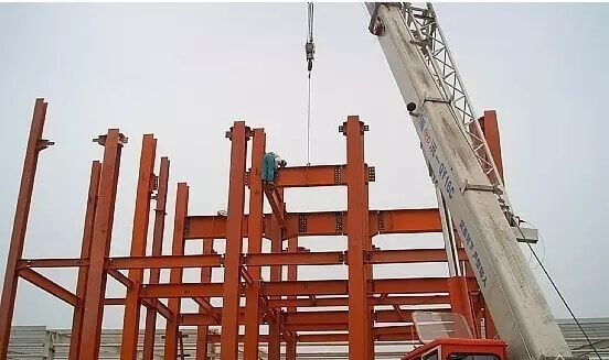
Installation sequence of portal steel structure
Select the two axes with column and horizontal bracing as the initial installation positions, and install the steel columns, inter-column bracing, and pipe strut.
Then, install the steel frame beams,inter-beam bracing, and horizontal bracing for the roof.
After forming a stable system, expand the installation backward.
When extending backward installation, follow the construction principles of steel columns, inter-column secondary steel structures, steel beams, and inter-beam secondary structures. Then, proceed with the construction of wall purlins and roof purlins.
Flange bracing, tie rod, diagonal tie rod, pipe strut, door columns, door beams, window columns, etc., should be installed along with the purlins. Once all the above work is completed and inspected, wall and roof panels will be constructed.
After the construction of wall and roof panels is complete, finish with the installation of the ridge cover for gable ends and the finishing attachments for door and window openings.
Factors of Portal Steel Frame Buildings that are considered in the design:
1. Regulations on the load value
Dead load
The design software generates the portal steel frame building’s self-weight, which calculates loads of the roof, purlin, bracing, and other components based on the actual design. The roof and wall panels can be corrugated single-color sheets or sandwich panels with insulation materials such as polystyrene foam, polyurethane, rock wool, glass wool, etc. The specific materials used in the design should be combined to determine the load of the roof and walls.
Variable load
Variable loads encompass live roofs, ash, cranes, seismic action, wind, and other factors. According to the “Technical Specification for Portal Steel Frame Light Steel Structures” (CECS102: 2002), the live load on the roof should be 0.5 kN/M2. However, if the load area exceeds 60M2, a reduction factor 0.6 can be applied, resulting in a typical steel frame calculation of 0.3kn/m2.
2. Minimize the amount of steel
The primary steel frame and purlins constitute over 90% of the steel consumption in portal steel frame buildings. Moreover, the arrangement of column spacing significantly impacts steel consumption under the same load conditions. Statistical analyses suggest that the recommended column distance is between 6-8m, and the span should not exceed 36m. Purlins should be thin-walled C and Z-type steel, while H-shaped sections are typically used for steel frames.
3. The design points are as follows:
(1) Since the portal rigid frame structural members have minor bending and torsional stiffness, and the overall stiffness is relatively weak, necessary measures should be considered during design to prevent bending and torsion of the components during transportation and installation. Deformation.
(2) Pay special attention to the arrangement of the bracing system and corner braces, as well as the connection structure of roof panels, wall panels, and components, to ensure that they can effectively participate in the work of the overall system.
(3) Since the component bars of the portal frame are relatively thin, the requirements for production, installation, and transportation must be considered during design.
(4) The impact of corrosion on the weakening of the cross-section strength of structural components must be fully considered in the design.
(5) The beams and columns of portal frames mostly use variable-section members. The strength after buckling should be considered when designing the webs of beams and columns, so plastic design is no longer applicable.
(6) The consequences of lightweighting must be considered and correctly handled in the design. For example, wind force may reversely act on lightweight roofs.
Features of the Portal Steel Frame Buildings
Less steel consumption and lightweight
The portal steel frame buildings comprise lightweight and multi-functional new roof and wall materials integrated with waterproofing and enclosure, significantly reducing the structure’s load weight. The load-bearing components are generally high-strength steel, which can reduce the structure’s weight. Usually, the importance of the portal steel frame is only 1/8-1/10 of the reinforced concrete construction and 1/2-1/3 of the weight of the ordinary steel structure, which fully reflects the advantages of new materials.
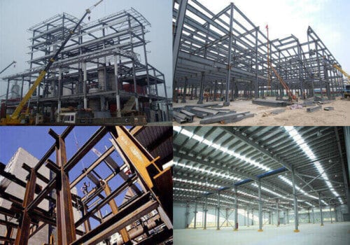
The construction speed is fast.
The degree of industrialization is high, the construction period is short, and the steel structure is easy to manufacture. Because the essential components, such as beams and columns of the portal steel frame, are shaped and manufactured in the factory, they are assembled on-site according to requirements, which speeds up the construction progress and shortens the construction period.
The period of the concrete bent structure is shortened by at least 60%. For generally small-scale industrial plants, the portal steel frame only takes 50 days to 2 months, while the reinforced concrete bent structure takes 10 to 12 months.
The fire protection solution of the portal steel frame buildings
Although steel is a non-combustible material, it is easy to conduct heat, and its fire resistance limit is only 15-20 minutes. For steel structures without fire protection, when the temperature reaches 350°C, 500°C, and 600°C, its strength will be reduced by 1/3, 1/2, and 2/3, respectively. When the structure’s temperature reaches 600°C, it will ultimately lose its bearing capacity. The surface of the steel structure can be covered with fire-resistant paint to prolong the fire-resistant time.
Related Posts