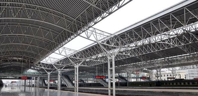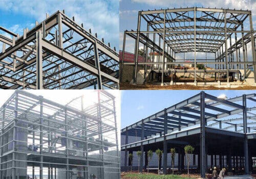

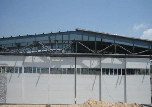


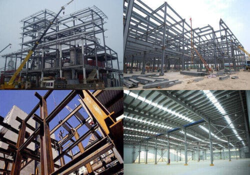


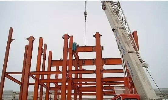
The steel structure buildings are the building in which the load-bearing structure made of building steel. The main structure is…
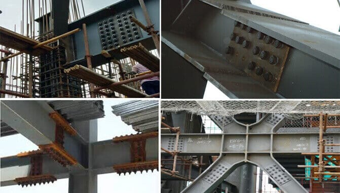
Steel structure splicing includes splicing in the workshop and on-site. The splicing methods include welding and bolting. We should implement steel structure splicing based on ensuring the strength of the components.
1. Steel structure splicing for uniform cross-section
Steel structure splicing at factory
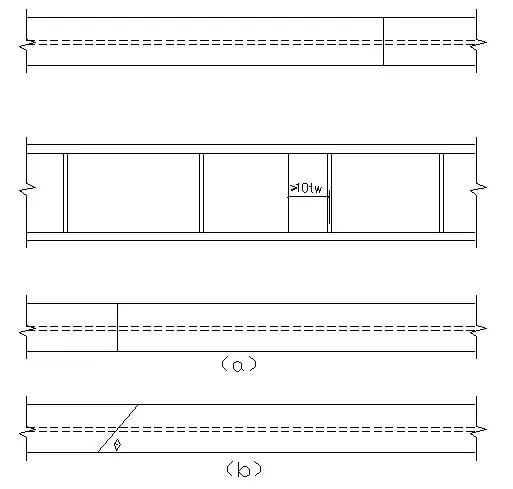
Tension-bearing components: direct butt welding (figure a) or splicing plate plus fillet welding (figure b) can be used. When direct butt welding, the weld quality must meet the Class I or II quality standards; otherwise, splicing plates and fillet welds must be used.
Pressure-bearing components: direct butt welding (figure a) or splicing plate plus fillet welding (figure b) can be used.
When splicing plates and fillet welds are used, the components’ flanges and webs should have their own splicing plates and welds to make the force transmission as direct and uniform as possible to avoid excessive stress concentration. When determining the web splicing plate’s width, it is necessary to leave enough space for operating the welding rod when welding the longitudinal weld.
Steel structure splicing on-site
Tension-bearing components: splicing plates can add high-strength bolts (Figure c) or endplates to add high-strength bolts (Figure d).
Pressure-bearing components: Welding (pictures e, f) or the upper and lower contact surfaces can be flattened and directly pressure-bearing transmission force (pictures g, h). When welding, the upper part of the component should be beveled in the factory in advance. The lower part (or the upper and lower two parts) has positioning parts (channel steel or angle steel) to ensure the correct position when welding. When the upper and lower contact surfaces are planed flat and topped, they should be supplemented with a small number of welds and bolts when they are directly pressure-bearing and force-transmitting so that they cannot be moved. The splicing of the tension and compression components should be calculated according to the principle of equal strength; that is, the splicing materials and connectors can transmit the broken section’s maximum internal force.
2. The splicing of steel beams
The splicing of beams is divided into splicing at the factory and on-site splicing due to different construction conditions.
Steel structure splicing at factory
1) It is best to stagger the flange and web positions to avoid the concentration of welds.
2) The splicing welds of flanges and webs generally adopt butt welds.
3) Check and calculations are not required for welds that meet the weld quality inspection levels of Class I and II.
4) Check and calculations are required for welds that meet the Class III weld quality inspection level. When the weld strength is insufficient, oblique welds can be used. When θ satisfies tgθ≤1.5, check and calculation is not necessary.
Steel structure splicing on-site
1) For splicing on-site, generally, the flange and web should be disconnected at the same section to facilitate segmented transportation (Figure a). To make the flange plate have a certain amount of room for expansion and contraction during the welding process to reduce the welding residual stress, the length of about 500mm can be reserved in the factory without welding.
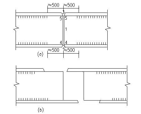
2) As shown in Figure b, the flange and web splicing positions’ proper staggering can prevent the welds from being concentrated in the same section, but it isn’t easy to transport.
3) For riveted beams and large welded beams that are more important or subject to dynamic loads, high-strength bolts are often used for jointing on site.
3. Connection of primary and secondary beams
The secondary beam is freely supported
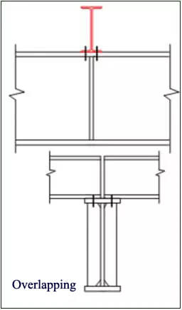
1). Overlapping
Structure: Support stiffeners should be arranged at the main beam’s corresponding positions to avoid excessive local pressure on the main beam web.
Features: Simple structure, convenient installation of secondary beams, but the main and secondary beam systems occupy a large net space.
Calculation: Generally, no calculation is needed, and the bolts are only used for fixing.
2). Side connection
Structure: The secondary beam is connected to the main beam’s side and can be directly connected to the stiffener of the main beam (Figure a, b) or the short angle steel (Figure c).
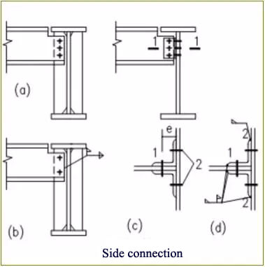
Features:
Figure a: It is connected to the stiffener with bolts, the structure is simple, and the installation is convenient, but one side of the upper flange and the lower flange of the secondary beam must be cut off;
Figure b: Site welds connect it. At this time, the bolts are only used for temporary fixing, but the welding of the welds at the ends of the secondary beam web is not convenient;
Figure c, d: To use short-angle steel angle steel to connect the main and secondary beams for bolt connection or installation welds, the upper flange needs to be partially cut off.
Calculation:
Figure a, b: The welds or bolts required for the connection should be calculated according to the secondary beam’s reaction force. Considering that the joint is not ideal, the secondary beam’s reaction force should be increased by 20~30%.
Figure c: When calculating the bolt ①, the short angle steel can be regarded as one body with the secondary beam. Therefore, the bolt ① should bear the secondary beam’s combined action supporting reaction force R and the moment M=Re. In contrast, the bolt ② only bears the role of R. Conversely. The short-angle steel can also be regarded as an integral part of the main beam. Then the bolt ① only bears the reaction force R, while the bolt ② should bear the combined action of the secondary beam support reaction force R and the moment M=Re.
Figure d: The calculation method is similar to Figure c. Weld ① and weld ② also assume the joint role of R or R and M=Re, respectively.
The secondary beam is continuous
The freely supported beam overlaps, except that the secondary beam passes continuously and is not broken on the primary beam. When the secondary beam needs to be spliced, the splicing position can be set at a small bending moment. Use bolts or welding to fix between the primary and secondary beams.
1). Overlapping
The freely supported beam overlaps, except that the secondary beam passes continuously and is not broken on the primary beam. When the secondary beam needs to be spliced, the splicing position can be set at a small bending moment. Use bolts or welding to fix between the primary and secondary beams.
2). Side connection:
Structure: To ensure the two-span secondary beam’s continuity at the primary beam, connecting plates must be provided at the upper and lower flanges.
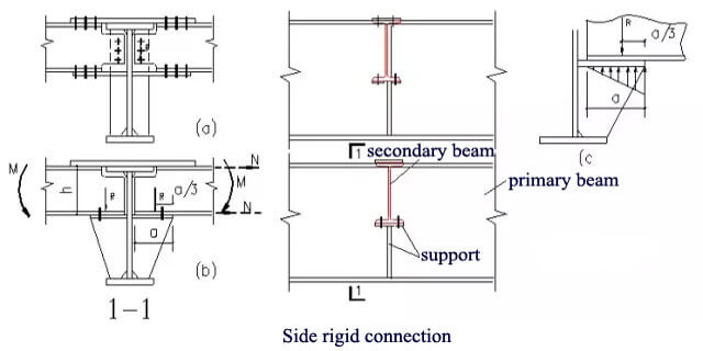
Figure a: Connected with high-strength bolts, the web of the secondary beam is connected to the stiffener of the primary beam, and the connecting plate of the lower flange is divided into two pieces, which are welded to both sides of the web of the primary beam.
Figure b: Installation on the site, welded connection, the secondary beam is supported on the support of the main beam, the upper flange of the secondary beam is provided with a connecting plate, and a supporting plate replaces the connecting plate of the lower flange.
Calculation:
The support’s reaction force is transmitted from the support to the main beam, and the upper and lower flanges bear the negative bending moment at the end. The connection, cover, and top plate transmit the horizontal force of M decomposition, F=M/h (h secondary beam height ) F is used to calculate the section size and the connection of the weld bolts. To avoid overhead welding, the connecting cover plate is narrower than the upper flange and the pull plate is wider than the lower flange.
4. Beam and column connection
For connecting nodes, the following basic principles should be followed:
Safe and reliable. The force analysis should be as close as possible to the actual working conditions. The calculation diagrams consistent with or close to the components’ actual connection status should be adopted; the connection should have a clear force transmission route and reliable structure guarantee.
It is easy to make, transport, and install. Reduce the type of joints; leave room for adjustment in the splicing size; try to facilitate operations during construction, such as avoiding overhead welding of site welds, setting up and installing supports, etc.
The economy is reasonable. The most economical method is determined after careful consideration of materials, production, construction, etc., and should not be understood as saving steel.
The beam-column connection can be divided into three types: flexible connection (hinged connection), rigid connection, and semi-rigid connection according to the different rotation stiffness.
Flexible connection of beams and columns
The connection between axial compression columns and beams is generally hinged.
1). The beam is supported on the top of the column
Figure a: The beam’s supporting reaction force is directly transmitted to the flange of the column. Leave a gap between adjacent beams so that there is room for adjustment during installation. The structure is simple and the construction is convenient. However, when the reaction forces of two adjacent beams are not equal, it will cause the column’s eccentric compression, and when the reaction force transmitted by one beam is large, it may also cause local buckling of the column flange.
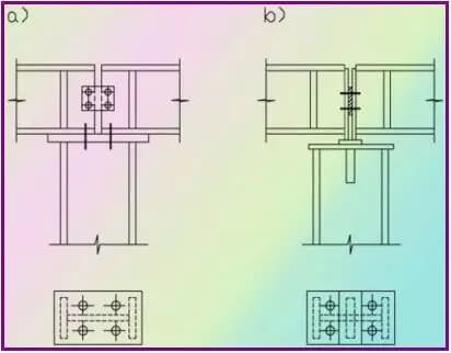
Figure b: Even if two adjacent beams’ reaction forces are not equal, the column is still compressed close to the axis. The bottom of the flange stiffener should be flattened and topped tightly against the column top plate; the column web is the main force-bearing part, and its thickness should not be too thin; under the column top plate, stiffeners should be provided, and the stiffeners should have sufficient length to meet The requirement of weld length and the requirement of uniform stress spreading.
The beam is supported on the side of the column
Figure a: When the reaction force of the beam is small, the beam can be placed directly on the corbel of the column without supporting stiffeners and connected with ordinary bolts; the structure is relatively simple, and the construction is convenient.
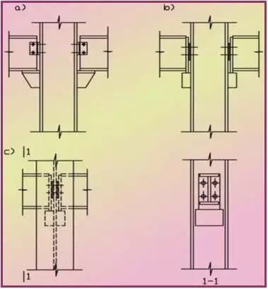
Figure b: Used when the beam reaction force is large. The reaction force of the beam is transmitted to the support by the end stiffener; the support is made of a thick steel plate (its thickness should be greater than the thickness of the stiffener) or stiffened angle steel, which is connected to the side of the column with a weld.
Figure c: Used when the reaction force of two adjacent beams differs greatly. The beam’s reaction force is transmitted through the web of the column so that the column is still close to the axial force state.
Rigid connection of beams and columns
Steel beams and columns generally adopt rigid connection.
The following requirements must be met:
Ensure that the bending moment and shear force of the beam section is reliably transmitted to the column; ensure the rigidity of the joints so that the connection does not produce obvious relative corners; the structure is simple and convenient for construction;
Figure a, b: The bending moment and shear force are directly transmitted to the column through the welding seam. It can be considered that the bending moment of the beam end is all transmitted to the column by the flange connection welding seam, and the shear force is transmitted to the column by the web welding seam.
To weld the flange connection weld at the flat welding position, the lining plate must be welded on the side of the column, and at the same time, notches are reserved in advance at the end of the beam web. The upper notch lets out the lining plate’s position, and the lower notch is to meet the welding requirements.
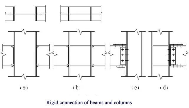
Figure c, d: The beam end bending moment and shear force are transmitted to the column through high-strength bolts and welds. Because the force can be transmitted to the column through the connecting plate and the angle steel, it belongs to indirect force transmission.
The beam can be provided with transverse stiffeners as shown in Figures b and d or not, as shown in Figures a and c, within the range where the beam is connected to the column. In the latter case, the strength and stability of the column web and flange must be checked.
Related Posts