
As the primary building material for steel structure industrial buildings, light steel structures directly affect the stability of the main…
Steel structure introduction covers the process and precautions for designing, fabricating, and constructing steel structures.
Design: Steel structure design is the core link of the whole project. Designers utilize professional calculation software to calculate and analyze the entire structure and ensure the structure’s safety, reliability, and economy to meet the building functions.
Fabrication: Steel structure fabrication is converting the design plan into essential components. Special equipment is used for cutting and welding to ensure each piece meets the design requirements.
Construction: Steel structure construction is assembling steel components into buildings according to the construction sequence, and site safety and construction quality need to be considered.
Steel structure introduction
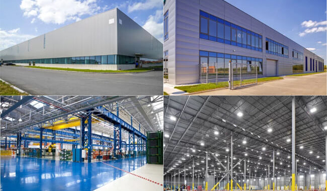
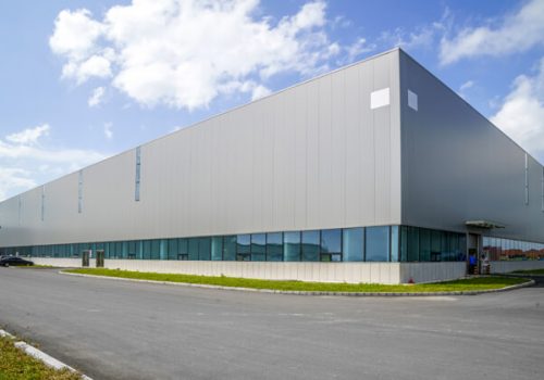
Steel structure refers to the essential components of section steel or steel plate and follows the use requirements through welding or bolt connection methods. According to specific rules, the load-bearing structure is called a steel structure. Steel structures are widely used in various engineering constructions, such as steel bridges, workshops, gates, large pipeline containers, public buildings, high-rise buildings, etc.
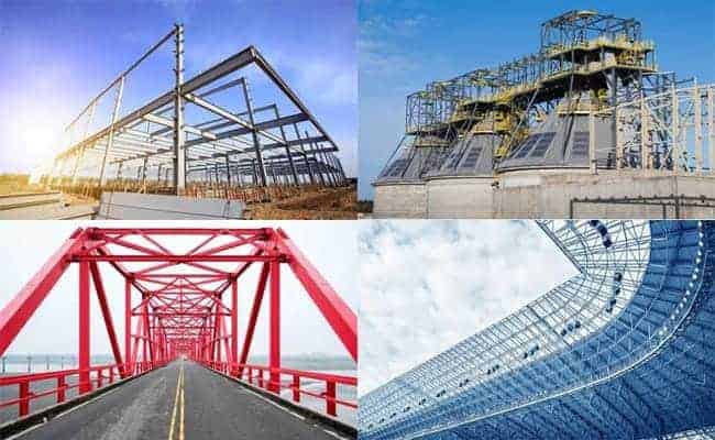
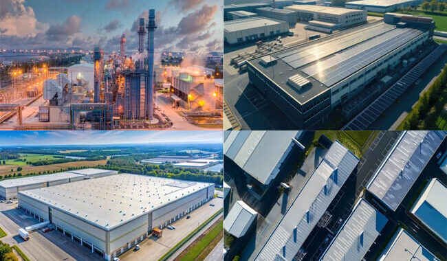
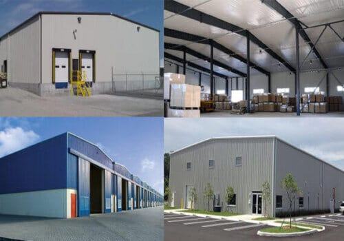
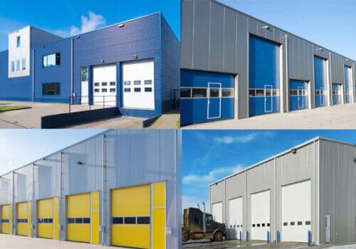
Application of steel structure:
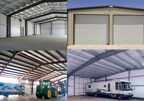
- Steel structures for buildings include multi-story buildings, factories, warehouses, commercial buildings, and steel villas.
- Offshore drilling platform built with steel structure
- Steel structures used in various large equipment
- Steel structure bridge
- Space grid steel structure, including grid structure, suspension cable structure, shell structure, pipe truss structure, membrane structure, etc.
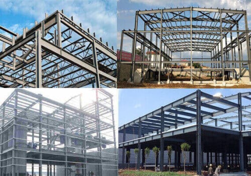
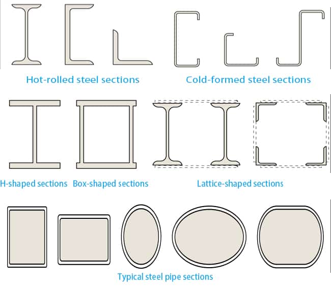
The Type of Steel structure components
Steel structure components can be made from hot-rolled or cold-formed steel, and composite components can be made from steel plates or sections. Typical hot-rolled steel sections include I-beams, channels, and angles, while cold-formed steel sections include C and Z-shaped sections. These components generally have small cross-sections, are lightweight, and have limited load-bearing capacity. For steel structures that require higher load-bearing capacity, composite components are often used, such as H-shaped sections welded from three plates, box-shaped sections made from four plates, or lattice-shaped sections made from I-beams and angles. Steel pipes are also an essential form of steel components, with better resistance to bending and torsion. Typical steel pipe sections include square, rectangular, circular, oval, and flattened oval shapes. Steel pipe components can be made from seamless steel pipes hot-rolled or cold-rolled from pipe blanks or welded steel pipes made from bending and welding steel strips or plates.
Steel structure design:
Design Methods
There are three methods to consider when designing steel structures: simple design, continuous design, and semi-continuous design.
Simple design
Simple design is the most traditional approach for connecting members without torque transmission. The structure’s resistance to lateral loads and sway is achieved through braces or a concrete core. Connection details are crucial to ensure no moments can adversely affect structural performance.
Continuous design
Continuous designs are more complex than simple designs. They assume that nodes are rigid and transfer moments between members. The frame’s anti-sway stability is achieved through the frame action, which requires software to analyze the structure. The actual combination of mode loads must be considered when designing consecutive frames. Connectors must withstand the moments, forces, and shear forces generated by the frame analysis.
Semi-continuous design
Semi-continuous designs are the most complex because they represent natural joint responses more realistically. Therefore, designers must closely track actual connection behavior, which requires complex computer programs. Two simplified procedures apply to braced and unbraced frames. In the wind moment method for unbraced structures, nodes are assumed to be fixed, and the lateral loads are borne by the frame action when gravity loads are considered. In the semi-continuous design of the Bracing frame, actual nodal behavior is thought to reduce the bending moment applied to the beam and reduce deflection.
Design steps of steel structure:
Conceptual design
In designing a steel structure, especially when selecting the structure type and determining the structure layout, it is a “conceptual design” that needs to be emphasized. Conceptual design refers to determining the control structure layout and detailed measures from an overall perspective based on the design ideas of the entire structural system and the mechanical relationship between components, failure mechanism, earthquake impact, test phenomena, and engineering experience. When problems are challenging to conduct precise rational analysis or not stipulated by the specification, conceptual design can be used to quickly and effectively conceive, compare and select. The structural scheme obtained from the conceptual design is usually easy to calculate by hand, the concept is clear, the qualitative is correct, and unnecessary cumbersome calculations can be avoided in the structural analysis stage. At the same time, it is the primary basis for judging the reliability of the computer’s internal force analysis output data.
When selecting a structure, it is necessary to consider the characteristics of different forms.
For example, in a prefab steel structure workshop building, you can consider using a grid structure instead of a portal frame if there is a large suspension load or moving load. Suppose the essential snow pressure in the area where the building is located is relatively high. In that case, the three-center circular reticulated shell structure can promote snow sliding and reduce snow load. Similarly, similar factors should also be considered if the rainfall is ample. Arranging supports in a frame structure can be more economical than a frame with simple joints. In buildings with large roof spans, suspension or cable-membrane structural systems with tension as the leading force can be selected. Steel-concrete composite structures are usually used in the design of high-rise steel structures. Still, in high-rise buildings with high seismic intensity or irregular structures, the form of a core tube plus an outer frame not conducive to earthquake resistance should not be chosen just for economic reasons. At this time, it is recommended to select the surrounding giant SRC columns as the structural system of the supporting frame.
When designing a steel structure building, it is necessary to consider many factors, such as the characteristics of the building, the distribution, and the nature of the force.
Building structures should generally have uniform stiffness and a transparent mechanical model. At the same time, the influence range of significant or moving loads should be reduced as much as possible so they can be directly transmitted to the foundation. Regarding the distribution of anti-lateral support between the columns, it should be uniform, and the centroid should be as close as possible to the line of action of the lateral force. Otherwise, the torsion of the building structure needs to be considered. To ensure the lateral resistance of the building structure, there should be multiple layers of defense. For example, if there is a bracing frame structure, each column should be able to support at least one-quarter of the total horizontal force individually.
Sometimes to meet different requirements, the layout of the floor plane secondary beams of the frame structure can be adjusted to change the direction of load transmission. Usually, to reduce the section, the secondary beams are arranged along the short path, but this may lead to an increase in the area of the main shaft, a decrease in the apparent height of the floor, and even pressure on the side columns on the top floor. At this time, supporting the secondary beam on the shorter main beam can protect the safety of the main shaft and column under the premise of sacrificing the secondary beam.
After the structural layout is completed, a preliminary estimate of the member section is required.
This mainly involves the assumption of the cross-sectional shape and size of members such as steel structure beams, columns, and Bracing.
Steel structure beams can be channel steel, rolled or welded H-section steel, etc. Usually, according to the load and support conditions, the section height is selected to be about 1/20~1/50 of the span. To simplify the calculation, the flange width can be determined according to the spacing and limit of lateral supports between beams. Once the section height and flange width are selected, the plate thickness can be estimated according to the local stability requirements in the code.
The cross-sectional shape of the column is usually estimated according to the slenderness ratio. Usually, the slenderness ratio is around 50<λ<150, and the simple selection value is about 100. Different force conditions allow steel pipe or H-shaped steel sections to be selected.
It should be noted that different structures have very other cross-section requirements. For example, in steel structures, special consideration should be given to the local stability of plates. Therefore, the criteria for limit values are also very different in the steel structure and light steel codes.
In short, there is no fixed requirement for selecting member section forms. However, structural engineers should reasonably choose safe, economical, and beautiful cross-sections according to the stress conditions of components.
Node design
The design of connection nodes is essential in the design of steel structure. Therefore, the form of nodes must be thoroughly thought out and determined before structural analysis. However, it is often the case that the final design of the joints does not precisely correspond to the format used in the structural analysis model, and this situation must be avoided.
According to different force transmission characteristics, nodes can be divided into rigid, hinged, and semi-rigid connections.
Connection method
Different connection methods have a significant influence on the steel structure. For example, although some rigidly connected nodes can bear bending moments, they will produce large rotations, which is inconsistent with the assumptions in structural analysis. This situation may lead to unfavorable results, such as the deformation of the actual project being more significant than the calculated data. Therefore, when designing connection nodes, it is necessary to pay attention to using the two commonly used methods of equal-strength design or actual force design.
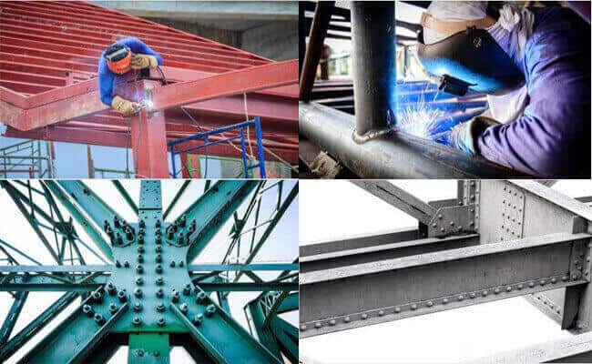
Welding Connection
Welding is a commonly used connection method in construction engineering, and the size and form of the weld seam must comply with the mandatory regulations of the code. Choosing a suitable welding rod compatible with the metal material to be connected is also necessary. For example, when connecting Q235 and Q345, you should select low-strength E43 instead of E50. In the welding design, the weld seam shall not be enlarged arbitrarily, and the center of gravity of the weld seam shall be as close as possible to the center of gravity of the connected components. For specific requirements, please refer to the regulations on weld seam structure in the specification.
Bolt Connection
Riveting is another connection method, rarely used in construction projects. Standard bolts have poor shear resistance and are suitable for secondary structural parts. High-strength bolts are increasingly used, and the commonly used strength grades are 8.8s and 10.9s. According to the force characteristics, it is divided into the pressure-bearing, and friction types, and the calculation methods are different. The minimum specification of high-strength bolts is M12, and the commonly used specifications are M16~M30. The performance of oversized bolts is unstable, so they should be used cautiously in design. Self-tapping screws suit the secondary connection between the plate and the thin-walled steel. Some low-rise wall panel houses are also commonly used to connect the main structure.
The thickness of the connecting plate can be taken as the thickness of the beam web plus 4mm, and the shear resistance of the net section can be checked. The design of the beam web needs to match the net section shear resistance of the web at the bolt hole, and the pressure-bearing high-strength bolt connection also needs to check the local pressure of the hole wall. In the design of joints, the construction space for installing bolts, on-site welding, etc., and the hoisting sequence of components must be considered to avoid errors that parts cannot be installed when transported to the site. In addition, workers should be able to locate and temporarily fix the site as conveniently as possible.
Component design
The first thing to consider in the component design process is the selection of materials.
Steel materials commonly used in different countries:
USA: ASTM A36, ASTM A572, ASTM A992, ASTM A514, ASTM A709, etc. Among them, ASTM A36 is one of the most commonly used low-carbon steel materials.
Europe: S235JR, S275JR, S355JR, S420MC, S460MC, etc. Among them, S355JR is one of the most commonly used structural steel materials.
China: Q235, Q355, Q420, Q460, Q690, etc. Q235B and Q355B are the most commonly used low-carbon steel materials.
Japan: SS400, SM490, SM520, SM570, etc. Among them, SS400 is one of the most commonly used structural steel materials.
The current code adopts the elastic-plastic method to check the section in the component design. However, this approach does not match the flexible approach to structural internal force calculations.
The current structural software provides the post-processing function of cross-section checking calculation. However, due to the advancement of program technology, some software can choose to increase the number of components that fail the check calculation from the given section library and automatically re-analyze it until it passes, such as SAP2000.
The following two points should be paid attention to when using the section optimization design function:
First, when the software checks and calculates the steel column section, the selection of the calculation length coefficient sometimes does not meet the code’s requirements. Therefore, structural engineers should check them individually, especially for components with complex node connections or variable cross-sections.
Secondly, when the estimated cross-section does not meet the requirements, two situations should be distinguished to increase the cross-section:
If the strength is insufficient, the thickness of the plates that make up the section can be increased. Among them, in the case of inadequate bending resistance, the thickness of the flange should be increased; in the case of insufficient shear resistance, the thickness of the web should be increased.
If the deformation exceeds the limit, usually the thickness of the plate should not be increased, but the height of the section should be considered; otherwise, it will be uneconomical.
Steel Structure Drawings
Steel structure design drawings are divided into two stages: design drawings and construction detail drawings. Steel structure companies or design units provide graphics, including schematic and component diagrams. Construction detail drawings are usually designed in-depth by steel structure manufacturing companies based on design drawings, covering all component processing and production details.
Design Drawings: They are the basis for manufacturing plants to prepare construction detail drawings and must include complete but not redundant depth and content. In the design drawings, it is necessary to clearly express the design basis, load data (including seismic action), technical data, material selection and material requirements, design requirements (including manufacturing and installation, welding quality inspection levels, painting, transportation, etc.), structural layout, component section selection, and the construction of the primary nodes of the structure. This helps the smooth preparation of construction detail drawings and can correctly reflect the design intent. The primary materials should be listed in the material table.
Construction detail drawings: Fabrication drawings must meet the workshop’s depth and content requirements for direct manufacturing. If there are different component units, they need to be drawn separately with detailed material tables attached.
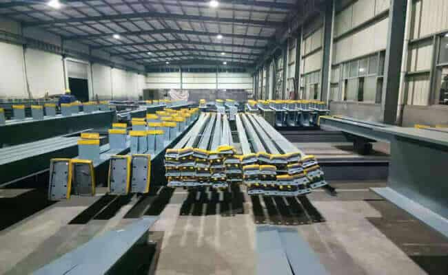
The process of steel structure fabrication
Lofting
In the first step, it is necessary to check the installation size and hole spacing of the drawing, release the nodes at a ratio of 1:1, and then check the size of each part. Next, make sample plates and sample rods as the basis for blanking size, bending, hole making, and other processing.
It is necessary to use the geometric drawing method on the workbench in a ratio of 1:1, and then use the steel plate to make the sample plate and the sample rod, and indicate the work number, drawing number, part number, quantity and aperture and other information on it. Then use the template and sample rod for numbering.
It is necessary to check the material, draw the processing position of cutting, drilling, etc., on the material, and mark the part number. At the same time, the model and sample rod should be appropriately preserved until the end of the project.
Note the following:
It is necessary to consider the processing allowance for milling, planing, and welded components and release the welding shrinkage according to the process requirements.
Operating according to the ingredient list and sample and saving materials as much as possible is necessary. At the same time, a cutting allowance should be set aside according to the cutting method.
Cutting
In the cutting process of steel blanking, commonly used methods include shearing, punching, sawing, and gas cutting. It would be best to decide based on requirements and conditions when choosing a specific way. For example, the cut steel should meet the criteria of no delamination and no cracks, and at the same time, it is necessary to remove the flash, slag, and spatter at the cut. In addition, the allowable deviation should meet the regulations for the method of gas cutting and mechanical shearing.
Gas cutting uses the high temperature generated by the mixed combustion of oxygen and acetylene to melt steel and blow away the slag through gas pressure to form a slot, to achieve the purpose of cutting metal. Mechanical cutting methods include sawing machines, grinding wheel cutting machines, shearing machines, and section steel punching and shearing machines. Plasma cutting is suitable for cutting materials such as stainless steel, aluminum, copper, and their alloys. This method has the characteristics of high cutting temperature, strong scouring force, good cutting edge quality, small deformation, and can cut any high melting point metal materials.
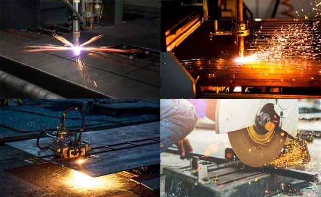
Therefore, when choosing a specific cutting method, it is necessary to consider the material’s actual needs and characteristics and choose the most suitable way to ensure the cutting quality. At the same time, the steel needs to be inspected and processed after cutting to ensure that the cutting quality meets the requirements.
Assembling
Before assembly, the steel must be straightened to correct its deformation. Contact surfaces must be free of burrs, dirt, or debris to ensure the components are assembled tightly and meet quality standards. In addition, appropriate tools and equipment, such as square steel rulers, should be available during assembly to ensure sufficient precision after the body is complete.
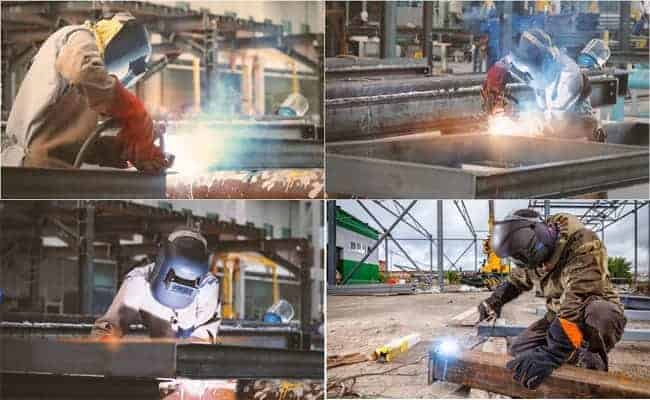
Welding
Welding is fusing two or more metal parts at high temperatures, which requires welding equipment.
Welding process:
- Steel columns and beams need to be welded, and this kind of welding adopts gantry automatic submerged arc welding. In addition, the column-beam connecting plate and the rib plate is manually welded. Automated welding must remove rust, burrs, dirt, etc., within the edge range to reduce the factors that cause defects, such as welding pores.
- The material of the arc starting plate should be the same as that of the parent metal, the form of the welding groove should be the same, and the length should meet the standard’s requirements. If the manual arc is used, an electric welding machine in good condition and complete functions is required, and the selected welding rod needs to be dried in a drying oven.
Straighten
In manufacturing steel structures, some problems will be encountered, such as deformation of raw materials, cutting deformation, welding deformation, transportation deformation, etc., which will affect the production and installation of components. To solve these problems, corrections are required. Discipline refers to counteracting deformations that have already occurred by creating new deformations. Several methods of straightening steel include mechanical straightening, manual straightening, and flame straightening. These methods can help us deal with deformation problems to ensure the quality and safety of steel structure fabrication.
Drilling
Drilling is an essential process in the manufacture of steel structures. There are usually two methods one is drilling, and the other is punching.
Drilling is the most common method used when fabricating steel structures. This method can be performed by hand or with a drill press and is especially useful for drilling holes with small diameters and thin materials: high drilling efficiency and precision. Punching is to create holes through punching force, but the quality of the hole wall is poor, so it is not commonly used to make steel structures.
In addition to drilling, there are reaming, countersinking, and reaming methods. Reaming is the enlargement of an existing hole to the required diameter. Countersinking is machining holes that have already been drilled on a workpiece. Reaming is to fine-machine the rough-machined holes to improve the surface roughness and precision of the holes. These methods can help make finer and more high-quality steel structures.
Small parts of manual welding
Small-parts manual welding is assembling the processed parts into a single component according to the requirements of the construction drawing, also known as assembly or assembly. During the assembly process, the size of the steel structure member should be determined according to factors such as the transportation road, site conditions, lifting equipment capacity, and allowable conditions for structural stress.
The following requirements need to be followed:
Before welding small parts, a sequence table should be compiled and assembled according to the sequence table.
It is necessary to carry out construction according to the processing number of the part and pay attention to the direction of the symmetrical part to avoid mistakes.
Components with large sizes and complex shapes should be divided into several simple parts and assembled into the whole piece.
The welded components shall be numbered according to the drawing, and the numbering position shall be designed to be prominent and easy to check.
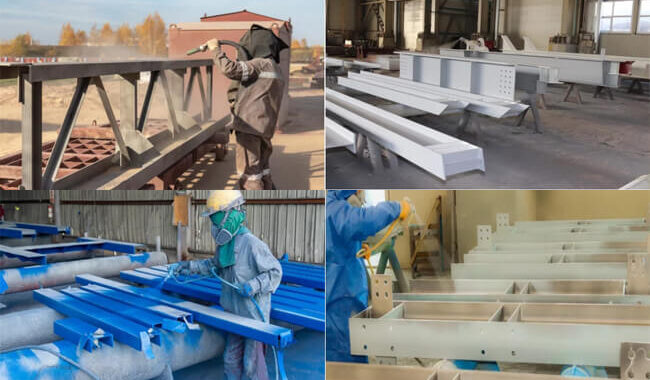
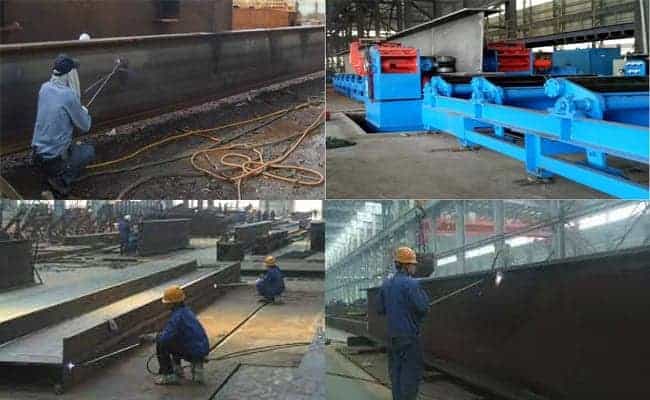
Rust removal:
To improve the anti-fatigue and corrosion resistance of steel, it is necessary to use special equipment for projectile derusting. This method can remove rust on the steel surface, increase its hardness, and facilitate the paint film’s adhesion without increasing the additional coating’s thickness.
When derusting, the abrasive must meet the quality standards and process requirements, and the relative humidity of the construction environment should not exceed 85%. After rust removal, tools such as brushes must remove residues on the steel surface before the next step can occur. If the surface of the steel after derusting has re-rusted, it needs to be de-rusted again.
Paint
After the qualified steel has been de-rusted, it must be painted with the first primer. Usually, after the derusting is completed, the primer can be painted within 24 hours if stored in the factory building. However, the primer should be applied on shift if stored outside the plant. When painting, the paint that meets the design requirements should be used; first, coat the primer, wait for it to dry, and then apply the intermediate paint and top coat to ensure that the thickness of the coating meets the design requirements. The color should be evenly brushed during brushing, and there will be no flow and drop.
Mark and packaging
Before packaging, mark each component according to the number specified on the design drawing, and keep it with pen, paint, or stickers on the components to identify them during packaging.
Particular attention should be paid to protecting components and coatings during transportation, especially parts prone to collisions, and proper protection needs to be provided.
If the component is deformed or damaged during the handling process, it should be repaired in time to ensure it is intact before shipment.
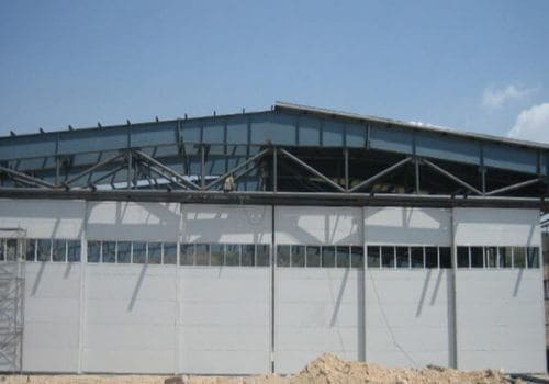
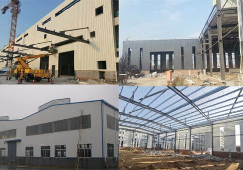
Steel Structure Construction
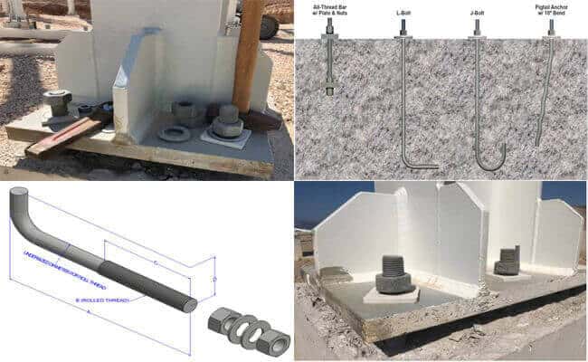
Construction of anchor bolts
The steel structure anchor bolt is a component that plays a fixed role in the building structure, and its construction process generally includes the following steps:
Process before construction:
Before entering the site, the anchor bolt components must be strictly checked and accepted to ensure that the selected raw materials meet the design requirements and must be reviewed and accepted according to the drawing requirements. At the same time, a comprehensive inspection of the specification, size, model, and appearance quality of the on-site anchor bolts should be carried out to ensure no damage.
Preparations before construction:
First, it is necessary to use the total station to measure, set out and position the embedded anchor bolts, and implement the actual data on the paper data. Secondly, the relevant anchor bolts must be prepared in advance because super long lengths and heavyweight often characterize these anchor bolts, and transportation and protection work needs to be done well. In addition, other auxiliary materials must be prepared, such as templates, reinforced steel, etc., to ensure the smooth progress of the entire project.
Operations during construction:
First, ensuring that the anchor bolts used can be manufactured according to the predetermined specifications is necessary. The anchor bolts’ installation and protection should be carried out after the formwork construction starts. In addition, it is also essential to ensure that the auxiliary materials used are entirely in place to ensure that there will be no problems during the construction of the entire project. Finally, the positioning template used in the anchor bolt embedding process must also have sufficient rigidity and accurate anchor bolt positioning holes to ensure that there will be no problems in the related anchor bolt embedding work.
Steel column installation:
Before installing the steel structure column, it is necessary to use the ink line to use the longitudinal and transverse axis reference lines of the foundation plane as the installation positioning line of the bottom column plate. At the same time, it is necessary to set the elevation observation point and the center line mark to ensure that the observation point and the mark-setting position of the steel structure project are consistent.
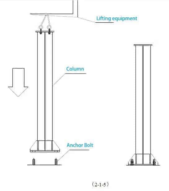
Hoisting machinery
The hoisting machine can be selected before hoisting according to the actual situation of the steel structure construction site. However, when boosting, it is necessary to put the installed steel structure column into the hoisting (lifting radius) position according to the work and direction. The hoisting machinery used in steel structure engineering installation mainly includes crawlers, tires, and rail cranes.
Hoisting
Before hoisting the steel structure column, a horizontal line should be drawn 500-1000mm up from the bottom plate of the column to review the plane elevation reference plane before and after installation and fixing.
Correction
The correction work of steel structure columns mainly includes plane position, elevation, and verticality.
Plane position centerline correction: When the longitudinal and transverse centerlines of the column bottom and the foundation do not coincide, the anchor bolts should be loosened first, and crowbars, sledgehammers, chain hoists, dry jacks, and other tools should move the anchor bolts. The plane displacement of the bottom of the column is controlled to control the deviation from the foundation’s vertical and horizontal centerline within the plate’s range of ≤ 5mm.
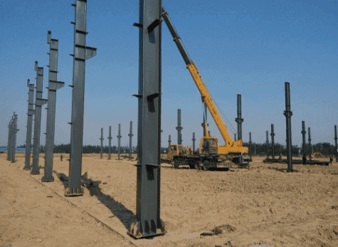
Correction of verticality of steel column: the installation of steel column must control the verticality deviation value of vertical and horizontal, and theodolite and wire hammer are often used to measure the deviation value.
Elevation correction: The elevation of the steel column shall be based on the elevation of the measured shoulder beam or corbel. The measurement method is to determine a fixed length from the corbel surface to the distance of about 1m from the bottom plate of the column, and then measure the fixed length from the corbel surface of each column downwards, and use the obtained point to make an elevation observation point sign. When hoisting the column, use a level to observe and control the elevation correction. If the deviation is too large, use the method of increasing or decreasing the bottom plate of the column to adjust so that the elevation observation marks of each column can be controlled on the same horizontal plane as much as possible.
Steel beam installation
Steel beams include roof beams and floor beams.
The process of installing the steel girders requires the use of some large equipment such as lifting equipment such as forklifts and lifts.
The specific steps are as follows: First, use a forklift or lift to lift the beam beyond the top of the column, then move the beam to the top of the column, align both ends as much as possible, and finally, place the beam down on the top of the steel column.
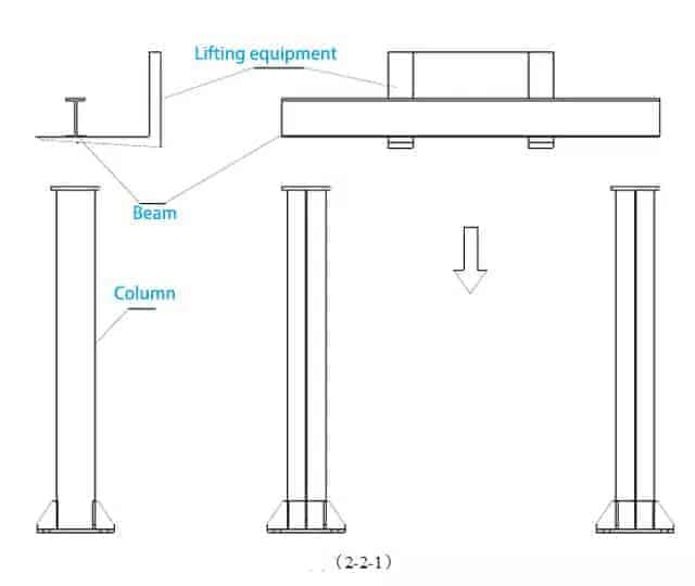
During installation, two workers must stand next to two columns and use climbing equipment for support. After the beam was stabilized, the two men used a hammer to precisely adjust the beam so that the center of the beam was aligned with the center of the column, and the length direction of the beam should be placed in the center according to the drawing. After the adjustment is completed, if it is the splint fixing method, install the splint first, put the splint above the bottom edge of the beam and align it with the bolt holes on the top plate of the column, connect the top plate of the column with the splint with bolts, and tighten and install the lock nut. Next, add flat and spring pads; if it is a welding connection, first fix the spot welding between the beam and the bottom plate of the column.
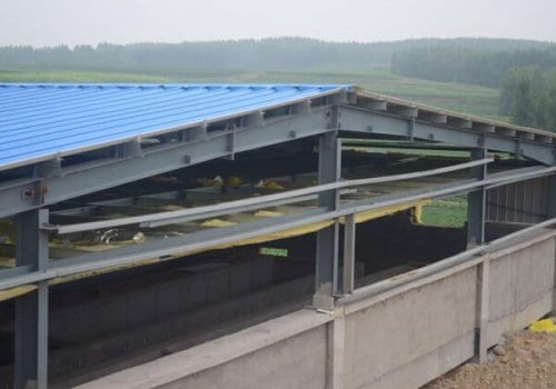
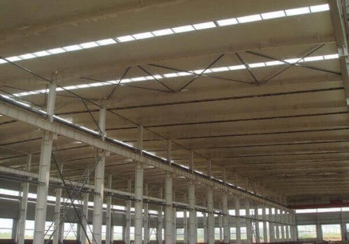
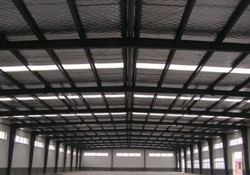
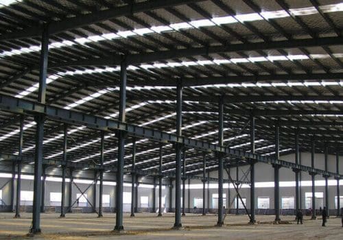
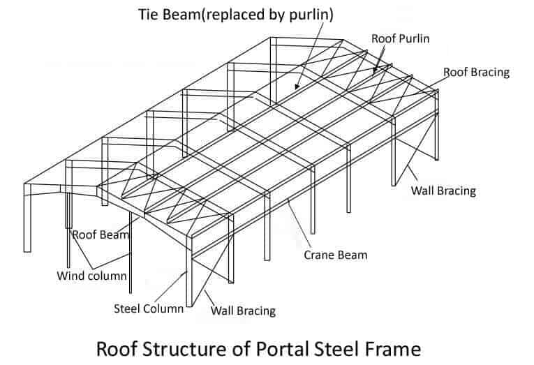
Components of a steel structure roof:
Steel beams support the entire roof structure, connected with steel columns by welding or bolting.
Roof purlins: C/Z type thin-walled steel with a 2-3mm thickness is used to fix the roof panels.
Tie beam: Used to connect steel columns or beams to increase the stability and bearing capacity of the entire structure.
Flange bracing: Connect purlins and steel beams to increase the bending strength and stability of the structure.
Horizontal Bracing: use round steel or angle steel to stabilize the roof.
Roof panel: Usually, a colored steel plate or composite panel covers the steel beam to form a roof panel.
The components of the steel structure floor:
Floor beams are the main structural components that support the floor slabs, carry the floor loads, and transfer them to the steel columns. Floor beams include main floor beams and secondary beams.
Floor slab: The floor slab is a planar structural member laid on the floor beams, usually made of the floor-bearing deck or prefabricated concrete slabs, which bear the floor load and transmit it to the floor beams.
Related Posts