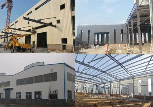
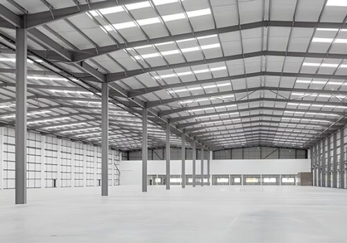
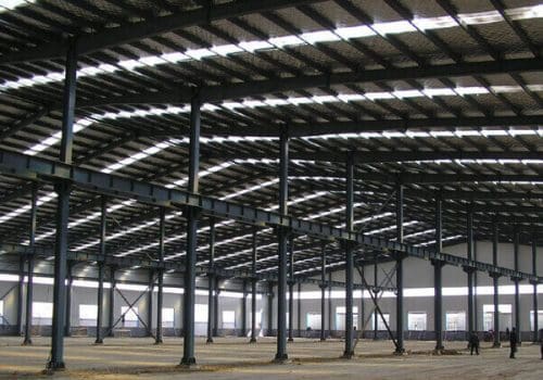
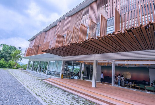
The service life of steel structure buildings is more than 50 years. The roof and wall panels of prefabricated steel…
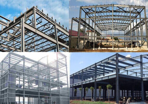
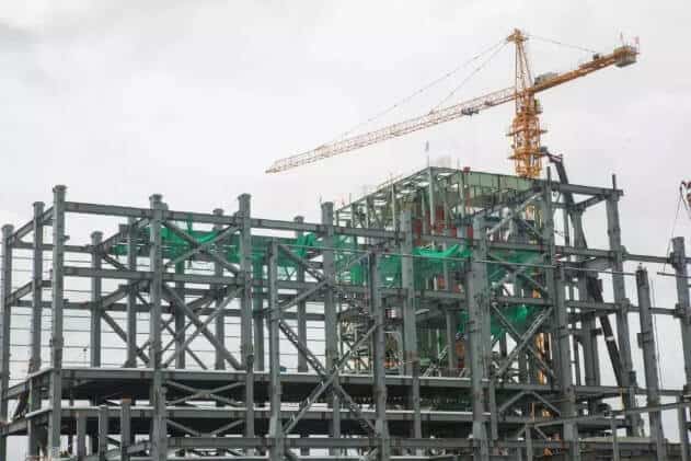
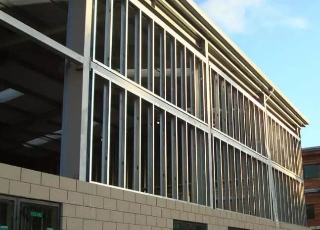
The steel frame structure is more common among steel multi-story buildings. The multi-floor steel frame structure comprises beams and columns; most nodes are rigidly connected. It is a typical vertical load-bearing structure.
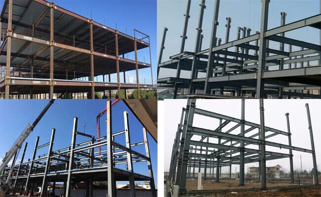
Design of Steel Structure Multi-story Building:
Floor Structure
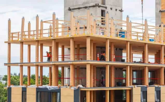
The floor has sufficient stability, strength, and rigidity. At the same time, the thickness of the floor slab should be reduced to increase the net height of the indoor. Corrugated metal floor deck-concrete composite floor covers are currently widely used.
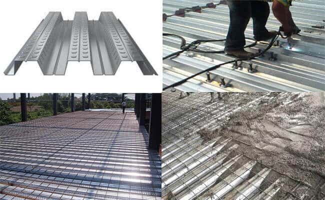
The construction speed is breakneck, the plane rigidity is also considerable, and the net height of the building is effectively improved. The general method is to lay the metal floor deck on the steel beams and then cast 100-150mm concrete on site. By welding enough shear studs on the steel beam, the steel beam and concrete can work together to form the floor.
Wall Materials
Lightweight wall materials have better thermal insulation and sound insulation performance. Currently, wall structures are mainly divided into self-supporting and non-self-supporting types.
Self-supporting walls generally use aerated concrete blocks as external walls. Light concrete boards, gypsum boards, or cement particle boards are used as interior walls.
External non-self-supporting wall materials generally include corrugated single-color sheets, sandwich panels, and glass fiber-reinforced exterior wall panels.
If non-self-supporting wall materials are used, a wall girt should be installed to hang the outer protective structure. Wall girt usually uses C or Z cold-formed thin-walled steel; the span and wall distance determine the size.
Different types of Steel Structure Multi-story Building :
Steel Frame Structure System
A pure frame system refers to a structural system composed of frames as the main components for bearing loads and resisting horizontal lateral forces in both the longitudinal and transverse directions.
The beams and columns of the frame should be rigidly connected.
Steel frame structures can generally be divided into two forms: unsupported frames and supported frames.
When the number of floors does not exceed 12, a system with a pure frame in one direction and a supported frame in the other can be used.
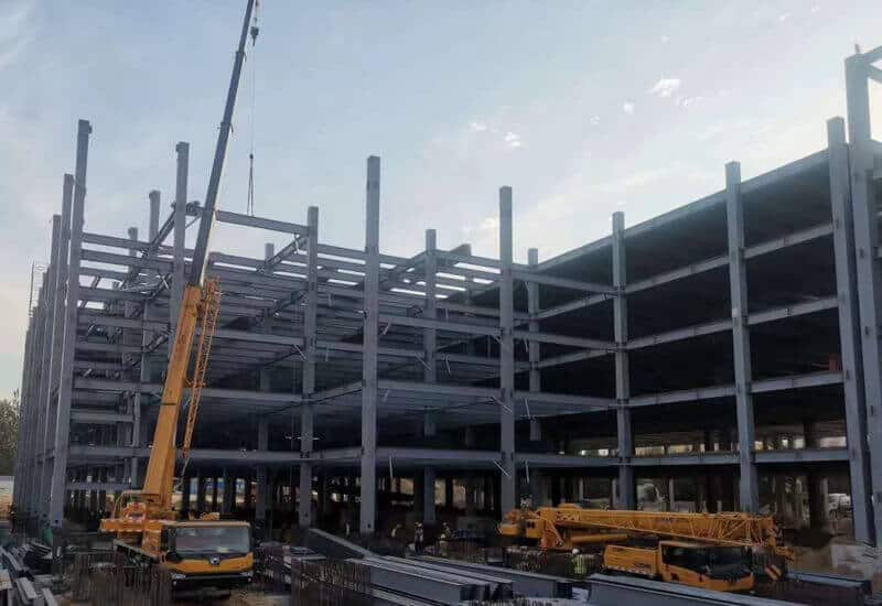
The unsupported pure frame system is composed of steel columns and beams. In earthquake zones, the longitudinal and transverse beams of the frame are generally rigidly connected to the columns, forming a spatial system in these directions. The system has muscular lateral stiffness and elasticity and can withstand earthquake effects in the two main axis directions.
Steel Frame Bracing System
The steel frame bracing system sets vertical supports between some frame columns in the frame system to form several bracing frames with vertical bracing, and the periphery is a rigid frame.
The bracing mainly bears the horizontal load of this type of structure. Under horizontal load, the rigid or elastic floor’s deformation is coordinated with the rigid frame to form a structural system with double lateral force resistance.
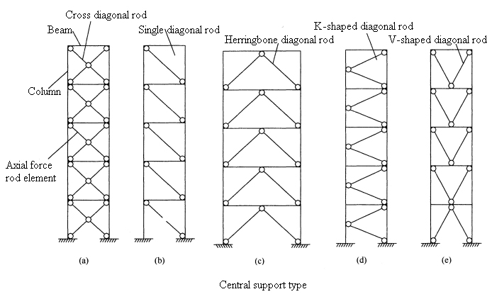
The bracing forms include central support, eccentric support, embedded steel plate, and other energy dissipation supports. When the general eccentric support cannot meet the structure’s lateral resistance requirements, other energy dissipation supports, such as embedded steel plates, can be used.
Central support: At each node of the central support, the axis lines of each rod must intersect at one point. According to the different arrangements of the diagonal rods, the central support can form cross-cross diagonal rods, single diagonal rods, herringbone diagonal rods, K-shaped diagonal rods, and V-shaped diagonal rods.
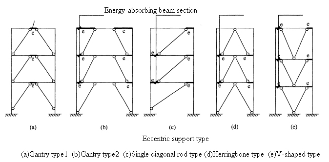
Eccentric support: The so-called eccentric support refers to the support that makes the support axis deviate from the axis of the beam and column in the structure.
Generally, at least one of the two ends of the supporting diagonal rod in the frame should intersect with the beam (not at the column node). The other end should intersect at the intersection of the beam and the column or deviate from the beam and column by a certain length and connect to another beam.
An energy-absorbing beam section, called eccentric support, is formed between the end of the supporting diagonal rod and the column.
Steel Frame Shear Wall System
A structural system in which a certain number of shear walls are arranged in a frame structure to make the frame and shear walls work together to resist horizontal loads.
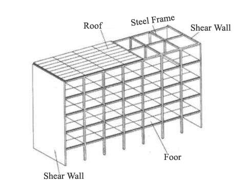
In the frame-shear wall system, the frame mainly bears vertical loads and a small number of horizontal loads, so the cross-sectional size is reduced compared to the frame system. However, it still has the characteristics of the flexible layout of the frame and convenient use. At the same time, due to the existence of the shear wall, it can bear more than 80% of the horizontal shear force, which significantly improves the lateral stiffness of the structure.
Frame: Core tube system
1. Stress characteristics
The frame-core tube system is formed according to the building’s use requirements. It is often used in office buildings, with the core tube as the primary lateral resistance structure system. The building uses the core tube as a service area for public facilities such as elevators and stairwells.
It forms an office area along the outer periphery of the core tube. The structure also includes a circle of outer frames arranged accordingly.
This core tube has a significant lateral stiffness, and the combination of the core tube and the outer frame constitutes a frame-core tube structural system. In this system, the core tube is the main lateral force resistance structure, and the frame-core tube system also has a double lateral force resistance structure.
2. Project Examples
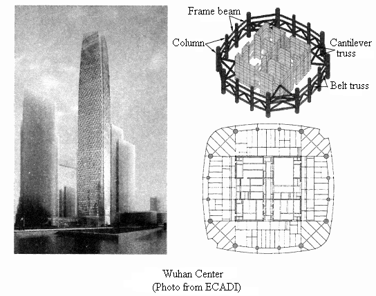
The Wuhan Center has a total construction area of 340,000 m2, 88 floors above ground and four floors underground, a height of 438m, and a plane size of 52.6 mX52.6 m. The entire structure adopts the “sparse column frame-core tube-cantilever truss system.
Cylinder structure
1. Frame-tube structure
(1). Force Characteristics
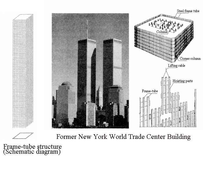
The frame-tube structure comprises dense columns and deep beams with small column spacing and high beam cross-sections around the building. The floor shear force is mainly borne by the web frame parallel to the horizontal force direction, while the web frame and the flange frame perpendicular to the horizontal force direction bear the floor overturning moment. The frame parallel to the lateral load plays the role of the “web” of the porous cylinder, while the frame perpendicular to the lateral load plays the role of the “flange.” The vertical gravity is partially borne by the outer frame and partially by the inner column or cylinder.
(2). Project Examples
The frame-tube structural system was first proposed by Fazlur Khan in the United States. He designed the first frame-tube structure, the 43-story Dewitt-Chestnut Apartment in Chicago, completed in 1965. The former World Trade Center in New York consists of two 110-story, 417-meter-high steel frame-tube structures. The plane size is 63.5mX63.5m, the standard floor height is 3.66m, the column distance is 1.02m, and the skirt beam height is 1.32m. A 7m high steel plate ring beam is set every 32 floors to reduce the shear lag effect.
2. Braced frame tube structure
(1) Force Characteristics
To provide users with an unobstructed broad view and a bright appearance, the building perimeter must adopt a larger column spacing and a shallower frame beam, a “sparse column, and a shallow beam” outer frame.
However, this structural system has a significant shear lag effect, cannot form the tube’s spatial impact, and has low lateral resistance efficiency.
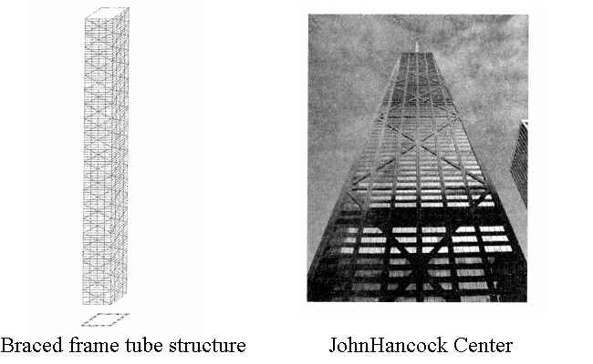
To this end, by setting large cross supports on each facade of the “sparse column and shallow beam,” the supporting diagonal bars of each plane intersect with the corner column at the corner of the frame tube at one point, ensuring the continuity of the support force transmission route. Thus, the structure forms a cantilever structure with overall force and good spatial effect. This structural system is called a supported frame tube.
(2). Project Example
The John Hancock Center, built in Chicago, USA, in 1970, has 100 floors and a height of 332m. It is a multifunctional building integrating offices, apartments, and hotels. Considering that the depth of the upper apartment cannot be too large, the entire building adopts a four-sided platform with a large bottom and a small top.
The plane size of the ground floor is 79.9mX46.9m, the plane size of the top floor is 48.6mx30.4m, and the maximum column distance of the ground floor reaches 13.2m, which is much larger than the 4.5m required by the frame structure.
3. Oblique grid tube structure
(1). Force Characteristics
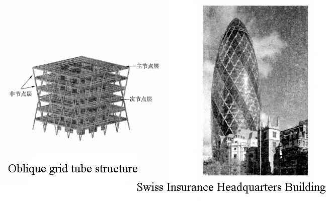
The oblique grid tube is a structural system that does not have “columns” in the general sense but uses mesh-like intersecting diagonal bars as components that simultaneously bear vertical and horizontal loads. The difference from the general frame tube structure is that the cross-arranged oblique columns replace the vertical column system in the conventional structure, making it an efficient mechanism for simultaneously bearing the vertical and lateral loads of the structure.
(2). Project example
The Swiss Insurance Headquarters Building, built in 2004, is located at 30 St. Mary Axe Street in the “City of London”, UK. It has 40 floors and is 180 meters high. It is an office building. The building adopts a circular peripheral radial plane, and its shape is like a bullet, which is spiral. The diameter of each floor plane changes with the curvature of the building. The diameter changes from 50 meters at the bottom to 56 meters (17th floor) and gradually narrows.
Bundled tube structure
(1). Stress characteristics
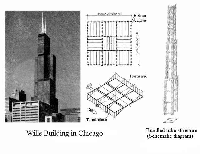
Two or more frame tubes are arranged closely in a “bundle” shape called a bundled tube. Compared with the frame tube, the bundled tube has more web frames, which means that the number of corner columns where the flange frame and the web frame intersect increases, significantly reducing the tube’s shear lag effect.
Therefore, compared with the frame tube structure, the east tube structure has greater rigidity and can form a more complex building plane shape. In particular, it is more effective to use bundled tubes when the side length of the outer frame tube is too large or the plane is narrow and long.
(2). Project examples
The most famous bundled tube structure is the Wills Building in Chicago, which is 443 meters high and has 110 floors. It is the tallest steel structure building in the world.
The plane size of the bottom floor is 68.6mX68.6m, with nine frame tubes below the 50th floor, seven frame tubes from the 51st to the 66th floor, five frame tubes from the 67th to the 91st floor, and two frame tubes above the 91st floor.
A ring truss is set along the outer periphery of the frame at the 35th, 66th, and 90th floors to improve the integrity and lateral stiffness of the structure. Adopting the bundled tube structure has increased the entire structure’s lateral efficiency from 61% to 78%.
Advantages of Steel Structure Multi-story Building:
Good seismic performance:
Due to steel’s excellent ductility, it can not only weaken the earthquake response but also make the steel structure able to resist substantial earthquake deformation.
Lightweight:
It can significantly reduce the vertical load and seismic action transmitted from the frame structure to the foundation.
Make full use of building space:
Due to the tiny column section, the building area can be increased by 2~4%.
The construction speed is fast:
An ample space is formed, the plane layout is flexible, the rigidity of each part of the structure is relatively uniform, the system is simple, and the construction is straightforward.
