


A steel portal frame structure is a type of low-rise building composed of steel columns and rafters joined by rigid…
What Are Steel Structure Beams?
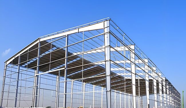
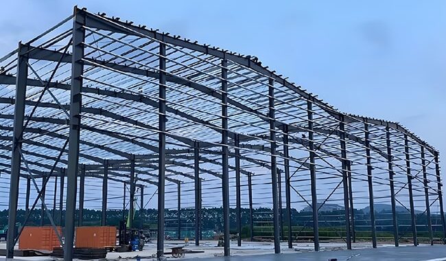
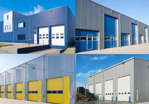
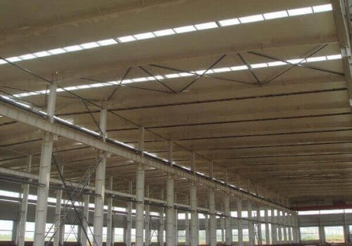
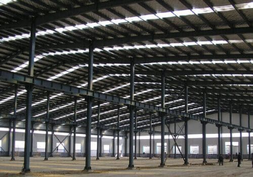
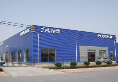
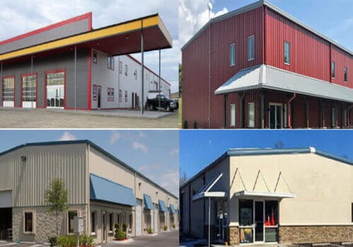
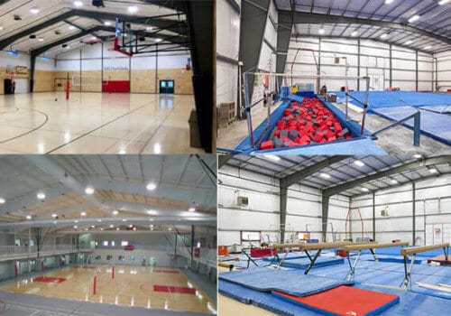
Steel structure beams are fundamental elements in modern construction, serving as the horizontal members that support and transfer loads across structural spans. Commonly employed in industrial buildings, multi-level frameworks, and steel warehouses, these beams ensure stability, enable architectural flexibility, and support both dead and live loads under various conditions. Their exceptional strength-to-weight ratio and adaptability make them indispensable in the design of efficient and durable steel buildings.
This article provides a detailed exploration of the classification, engineering design principles, fabrication process, transportation logistics, and installation techniques of steel beams, offering practical insights for engineers, designers, and construction professionals.
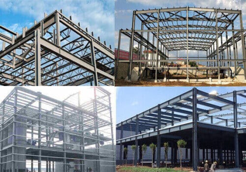
1. Classification of Steel Structure Beams and Their Applications
Steel beams are typically categorized based on their manufacturing process and structural behavior:
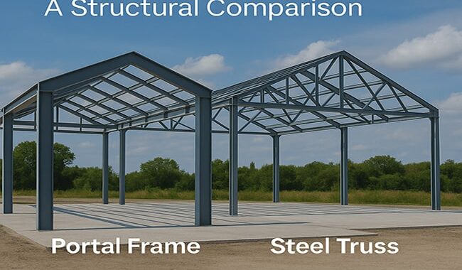
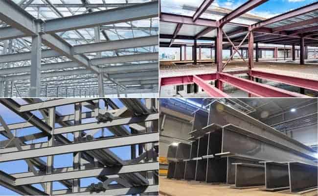
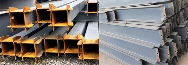
1.1 Rolled Steel Sections
Hot-rolled sections such as I-beams, H-beams, and channels are widely used in standard construction due to their ease of procurement and installation. Cold-formed C and Z-sections, on the other hand, are typically applied in secondary framing systems like purlins and girts, particularly when spans and loads are relatively small.
While convenient, rolled sections are limited in cross-sectional dimensions, making them less suitable for long-span or heavy-load scenarios.
1.2 Welded Composite Beams
When design demands exceed the capabilities of standard profiles, welded composite beams are introduced. These include:
- Welded H-beams, preferred for their balance between strength and fabrication simplicity.
- Box-section beams, which offer enhanced torsional rigidity but involve more complex manufacturing and higher material use.
Such custom-fabricated beams are essential in long-span workshops, crane runways, or where structural performance must be tightly controlled.
2. Design Methodology for Steel Structure Beams
Designing steel beams requires a rigorous and structured process, incorporating national codes such as GB50017, AISC 360, or Eurocode 3. The process encompasses both structural analysis and detailed checks to ensure safety, economy, and functionality.
2.1 Defining Structural Parameters
The initial phase involves specifying usage scenarios—span length, load characteristics (static or dynamic), floor-to-floor height, and clearance. Based on these, engineers develop a rational arrangement of primary and secondary beams that balances structural efficiency with architectural requirements.
2.2 Estimating Beam Depth
Beam height is typically derived from span-to-depth ratios:
- 1/10–1/15 for floor beams
- 1/20–1/25 for roof beams
The selected depth must satisfy both stiffness criteria and construction constraints such as headroom or embedded equipment.
2.3 Sectional Design and Material Selection
The cross-section is selected based on bending moment, shear force, and serviceability limits. Parameters include:
- Flange width and thickness
- Web depth and slenderness
- Yield strength of the selected steel grade (e.g., Q355, S355JR)
2.4 Structural Checks and Performance Validation
Strength Verification
Critical locations such as maximum moment zones, joints, and support regions must meet strength requirements under combined stresses.
Stability Assessment
Beams susceptible to lateral-torsional buckling must be evaluated. Factors include:
- Unsupported length
- Torsional stiffness
- Lateral bracing configuration
Designers must anticipate and mitigate any potential instability at an early stage, rather than relying on corrective adjustments after sizing.
Deflection Control
Deflection limits are governed by usage:
- L/250 for general floor beams
- L/600 for precision crane girders
Exceeding these can affect equipment alignment or user comfort.
Local Stability
To prevent local buckling in flanges and webs, code-specified width-to-thickness ratios must be respected. Additional stiffeners are often required in slender web regions.
Detailing and Connection Design
Comprehensive design includes:
- End connections (bolted or welded)
- Splice joints for long beams
- Anchorage systems at supports
- Integration with bracing or floor systems
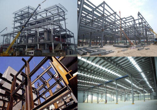
3. Fabrication Process of Steel Structure Beam
3.1 Cutting and Preparation
Steel plates are cut to required dimensions using CNC plasma or flame-cutting machines, ensuring precision and minimizing material waste.
3.2 Assembly and Welding
Flanges and webs are assembled into their final geometry—typically H or box shapes—before undergoing submerged arc welding (SAW). The welds must achieve full penetration and be inspected for defects.
3.3 Post-Weld Treatment
Post-welding correction includes:
- Heat or flame straightening
- Hole drilling
- Addition of end plates, stiffeners, and lifting lugs
3.4 Surface Protection
To prevent corrosion:
- Paint or primer coatings are used for indoor environments
- Hot-dip galvanizing is applied for marine or outdoor exposures
The chosen treatment must match the service environment and maintenance plan.
4. Transportation and Beam Splicing
Due to transportation length limitations, long beams are fabricated in sections:
- Factory Splicing: Performed during manufacturing. Web and flange welds are staggered for load distribution.
- Field Splicing: Conducted on-site using high-strength bolts or full-penetration welds. Splices should be placed in regions of low bending stress for efficiency and safety.
Proper planning of splice location and method is essential to ensure structural continuity.
5. Installation Best Practices
5.1 Site Storage and Preparation
Beams should be stored on level ground with wooden pads to avoid distortion. Inspection for straightness and damage is conducted prior to erection.
5.2 Lifting and Hoisting
Lifting points must be chosen to balance the beam’s weight. Wire ropes should be protected at contact edges, and hoisting angles should exceed 45° for stability. Taglines assist in directional control.
5.3 Placement and Connection
Beams are slowly positioned over supports. Installers align bolt holes, insert high-strength bolts, and complete required welds. All procedures should comply with safety protocols and quality control standards.
Conclusion
Steel structure beams form the backbone of steel-framed buildings, facilitating load transfer, spatial efficiency, and architectural flexibility. A successful beam system depends not only on correct sizing but also on proper detailing, fabrication, transportation planning, and safe installation.
By following best practices in beam design and execution, engineers can ensure long-lasting, high-performance structures capable of meeting diverse industrial and commercial needs.
At Havit Steel Structure, we provide tailored beam design, precise fabrication, and professional installation guidance to support your project from concept to completion.
FAQs – Steel Structure Beams
Q1: How do I choose between hot-rolled and welded steel beams?
Hot-rolled beams are ideal for standard spans and loads, while welded beams offer custom solutions for heavier or longer applications.
Q2: What is the most critical factor in beam design?
Stability and deflection control are often as important as strength. A well-designed beam must remain stable under load and limit deflection within acceptable limits.
Q3: Can steel beams be galvanized?
Yes. Galvanizing protects against corrosion, especially in humid or outdoor environments.
Q4: What are typical deflection limits for steel beams?
Depending on usage, limits are generally:
L/250 for floor beams
L/600 for crane beams
Q5: Are bolted splices reliable for long beams?
Yes. When properly designed and installed, bolted field splices offer excellent structural continuity and ease of installation.
Related Posts